
Installation Instructions Instruction Manual


H & H Specialties Inc. 600 Series Installation
South El Monte, CA 91733 February 20, 2007
Page 2 of 3
proper alignment of the track sections may not be possible.
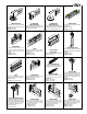
5. Attach the double end pulley (603)to one end of the track.
From the other end insert single carriers (601, 616, or 628) and
the insert the master carrier (642, 647, or 649) into the track.
Finish by attaching the single end pulley (604A). NOTE: For
one-way operation a 604A single end pulley should always be
used.
6. If the track is being suspended from a counterweight system,
balance the system now. WARNING! After attaching track
to a counterweighted batten, make sure to balance the line
set and leave at a comfortable working level.
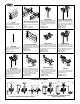
7. Start to reeve the hand line from the upper sheave of the
double end pulley. The rope goes over the sheave and through
the top sheave of the double spindles (618). In one-way track
installations, the double spindle is the only spindle used.
8. Reeve the hand line around the sheave of the single end
pulley and back to the master carrier. Terminate the hand line
into the rope clamp of the master carrier..
9. Reeve the other end of the hand line through the tension
spring floor block and up to the double end pulley. The spring
in the tension block should be extended when operating line is
first reeved. Reeve the handline over the sheave and terminate
at the master carrier. Remove slack in line and tighten cord
clamps. Release spring in floor block to place line under
tension. CAUTION! Exercise care when releasing tension in
spring to avoid injury. For counterweight batten mounted
tracks a 643 Sand Bag Tension Pulley should be used.
C. CEILING MOUNT INSTALLATION
Ceiling mounting the 600 Series is similar to the batten
mounting procedures. The following considerations should be
followed when ceiling mounting.
1. After laying out the track, use a plumb line or laser to locate
positions of the ceiling hangers relative to the track. Use
appropriate attachment methods for the individual job
conditions. Before installing ceiling hangers (611) make sure
that the ceiling is parallel to the floor. Shims may need to be
installed to compensate for irregularities.
2. After the hangers are installed, raise the track in sections and
attach to the ceiling hangers. In many cases, ceiling hangers can
be installed onto the track, then raised to the ceiling for
mounting of the hanger.
3. Rig track for either bi-parting or one-way travel.
D. SPECIAL INSTRUCTIONS
Spindles
1. For 600 Series tracks a radius of 4'-0" is recommended for
ease of operation. Tighter curves are possible and will result in
a system that requires additional effort to operate. For these
applications, consult the factory.
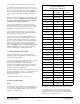
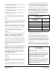
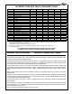
RECOMMENDED SPINDLE & IDLER SPACING FOR
CURVED 600 SERIES TRACKS
(based upon 90 degree curve)*
Radius Spindle/Idler
Spacing
Suggested
Quantity
2'-0" consult factory consult factory
3'-0" consult factory consult factory
4'-0" 15" 6
5'-0" 16" 7
6'-0" 20" 7
7'-0" 22" 7
8'-0" 25" 7
10'-0" 32" 7
12'-0" 38" 7
14'-0" 38" 8
16'-0" 42" 8
18'-0" 48" 8
20'-0" 52" 8
22'-0" 60" 8
24'-0" 57" 9
26'-0" 61" 9
28'-0" 66" 9
30'-0" 71" 9
32'-0" 75" 9
36'-0" 75" 10
40'-0" 75" 11
44'-0" 75" 12
48'-0" 75" 12
52'-0" 75" 14
56'-0" 75" 15
60'-0" 76" 16
64'-0" 76" 17
68'-0" 76" 18
*For manual cord-operated tracks with a radius of 8'-0" or less,
the addition of one spindle and idler will help ease of operation
2. In locating spindles, place so that the cord is adequately
supported as it turns the corner. Use the following chart for
reference only. Due to site conditions, the numbers of spindles
required for ease of operation may vary.