
Installation Guide

`
V
apor Tight Series Installaon Guide
SAFETY INSTRUCTIONS:Read instrucons carefully before aempng to install fixture.
All wiring should be performed by a qualified electrician.
Disconnect power before installing or servicing. This fixture must be wired in accordance with the Naonal Electrical
Code and applicable local codes and ordinances.
CAUTION: Risk of file
WARNING: Make certain power is OFF before installing or maintaining fixture. No user serviceable parts inside.
WARNING: Do NOT handle energized fixture when hands are wet, when standing on wet or damp surfaces or in
water.
WARNING: Fixture to be independently supported to building structure.
CAUTION: Be sure the fixture temperature is cool enough to touch. Do NOT clean or maintain while the fixture is energized.
1. Clean lens with non-abrasive cleaning soluon.
2. Do NOT open fixture to clean the LED. Do NOT touch the LED.
Note: These instrucons do not cover all details or variaon in equipment, nor do they provide for every possible situaonduring
installaon, operaonor maintenance.
1. Check that the line voltage at fixture is correct. Refer to wiring direcons.
2. Check that the fixture is grounded properly.
Universal voltage driver permits operaonat 120V through 277V, 50/60Hz.
1. Connect the BLACK fixture lead to the (+) LINE supply lead.
2. Connect the WHITE fixture lead to the (-) COMMON supply lead
3. Connect the GROUND wire from fixture to the supply ground. Do NOT connect the GROUND of the dimming fixture
to the output.
4. Connect the VIOLET fixture lead to the (V+) D
IM lead.
5. Connect the GRAY fixture lead to the (V-) DIM lead.
CLEANING&MAINTENANCE:
TROUBLESHOOTING:
0-10V DIMMABLE WIRING:
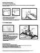
Schematic of Wattage adjustment (3 set positions, see right Fig. )
Model Left Postion
2nd Postion
(From left to right)
3rd Postion
(From left to right)
LHB-1-WS-40-U
LHB-1-WS-50-U
70W
LHB-2-WS-40-U
LHB-2-WS-50-U
LHB-3-WS-40-U
LHB-3-WS-50-U
LHB-4-WS-40-U
LHB-4-WS-50-U
90W 110W
110W 135W 160W
180W 200W 220W
240W 280W 320W
1
2
3
4
1.Set slip switch to
left position
2.When the slip
switch is set to centre
position
3.Set slip switch to
right position