
Instructions / Assembly

3
Installation Steps:
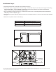
5. Unscrew and remove the cover plate from the driver box. (Fig. 3)
6. Insert power supply using appropriate electrical ttings. Insert BLACK wire (Line) from the power supply into the wiring
terminal marked with L. Insert the WHITE wire (Neutral) from the power supply into the wiring terminal marked
with N. Connect the green wires (ground) together. (g. 4)
7. For 0-10V dimming circuits, wire the grey (-) and purple (+) wires to the corresponding wiring terminals marked with
GND (Grey) and 0-10V (Purple). (g. 4)
8. For thru-wiring to another luminaire, utilize the second set of terminals marked “L” and “N” in the same manner detailed
in step 6.
9. Reattach cover plate to driver box after wiring.
Ceiling Designation Fixture Dimensions: in. (mm)
2x2’ 23.62”x23.62”x1.81”(600x600x46mm)
2x4’ 23.62”x47.24”x1.81”(600x1200x46mm)
0-10V Dimming
Grey (GND)
Purple (0-10V)
Green (GND)
White (N)
Black (L)
4
© 2017 Halco Lighting Technologies, LLC. All rights reserved. Halco and ProLED are registered trademarks of Halco Lighting Technologies. Warranty@halcolighting.com
All sizes and specications are subject to change. Print Edition 07-25-17
Halco Lighting Technologies | 2940 Pacic Drive | Norcross, GA 30071 | Toll Free 800.677.3334 | Phone 770.242.3612 | Fax 800.880.0822 | Email customercare@halcolighting.com | Atlanta | Carlstadt | Chicago | Cleveland | Houston | Phoenix