
Installation Guide


Page 6
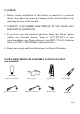
PARTS INCLUDED FOR INSTALLATION (parts are not to scale):
1 Nipple (#6) 2 Outlet Box Screw (#9) 1 Ground Screw (#7)
1 Crossbar (#10) 3 Wire Connector (#8) 1 Cap Nut (#3)
INSTALLATION INSTRUCTIONS:
1. Attach the Crossbar (#10) to the Outlet box (#5) using two Outlet Box Screws (#9).
The side of the Crossbar marked “GND” must face out.
2. Thread the Nipple (#6) part way into the center hole of the Crossbar (#10).
3. Connect the white wire from the fixture to the white wire from the Outlet Box (#5),
and the black wire from the fixture to the black wire from the Outlet Box (#5). Cover
the two wire connections using the two provided Wire Connectors (#8). Wrap the
two wire connections with electrical tape for a more secure connection. If your outlet
box has a ground wire (green or bare copper), connect fixture’s ground wire to it
using the wire connector (#8). Otherwise connect the copper ground from the fixture
to Ground screw (#7) on the Crossbar (#10). Note: If you have electrical questions,
consult your local electrical code for approved grounding methods.
4. Place Backplate (#1) through Nipple (#4) and secure it tightly using Cap Nut (#3).
5. Install the light bulb (not included) in accordance with the fixture’s specifications.
(DO NOT EXCEED THE MAXIMUM WATTAGE RATING!!)
6. Installation is complete. Turn on the power at the circuit breaker or fuse box. Turn
the light switch on to activate the fixture.