
Installation Guide


9
HAMPTONBAY.COM
Please contact 1-855-HD-HAMPTON for further assistance.
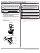
Assembly - Hanging the Fan (continued)
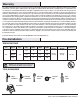
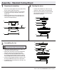
Hanging the fan
2
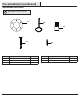
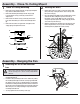
Making the electrical connection
3
IMPORTANT: Use the plastic wire connectors (CC) supplied with
your fan. Secure the connectors with electrical tape and ensure
there are no loose strands or connections.
WARNING: Each wire not supplied with this fan is designed to
accept up to one 12-gauge house wire and two wires from the
fan. If you have larger than 12-gauge house wiring or more
than one house wire to connect to the fan wiring, consult an
electrician for the proper size wire nuts to use.
□ Carefully lift the fan-motor assembly (F) up to the slide-on
mounting bracket (A).
□ Insert the ball portion of the ball/downrod assembly into the
socket of the slide-on mounting bracket.
□ Turn the ball/downrod assembly clockwise until it is seated
with the tab of the slide-on mounting bracket aligned with the
slot in the ball.
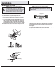
□ If using close-to-ceiling mounting, hang the fan on the hook
provided by utilizing one of the round holes at the outer rim of
the ceiling canopy (C).
WARNING: The hook (OO) is only to balance the fan while
making the electrical connections. Failure to hang as shown
may result in the hook (OO) breaking, causing the fan to fall.
The hook must pass from the inside to the outside of the
canopy.
WARNING: When hanging the fan on the hook (OO) it is
critical that you use one of the non-slotted (round) holes in
the canopy (C).
□ Please refer to WINK remote installation
instructions at the beginning of this
document.
NOTE: The fan comes with 30 in. lead wires for use with an
extended ball/downrod assembly. If using the 4.5 in. ball/downrod
assembly (B) provided, you can cut the lead wires to your desired
length (no shorter than 12 in.).
WARNING: Remove the rubber motor stops on the bottom of the
fan before installing the blades or testing the motor.
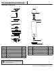
Standard mount.
Close to ceiling mount.
E
F
B
D
C
A
A
C
D
F
OO