
Installation Guide


13
HAMPTONBAY.COM
Please contact 1-855-HD-HAMPTON for further assistance.
Assembly - Attaching the Switch Cup
Attaching the switch cup
1
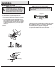
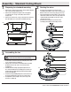
□ Remove the four screws on the black plate below the fan mo-
tor assembly (E).
□ Connect the adaptor plug exiting the bottom of the motor
with the plug from the switch cup (F). Be sure the plugs
connection snap together completely.
□ Mount the switch housing to the black plate below the motor by
aligning the four screw holes and securing with the four screws
that were removed in the step 1.
□ Attach the pull chain extension (EE) to the fan pull chains.
CAUTION: To reduce the risk of electric shock, disconnect
the electrical supply circuit to the fan before installing the
light xture.
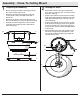
NOTE: Notice the location of the fan’s slide switch. This is the
switch used to change the fan’s directional rotation. For more
information on the operation of this switch, see Operating
Your Fan on page 13.
Turn on the power and check the operation of the fan. The fan pull
chain controls the fan speed as follows:
1 pull - High, 2 pulls - Medium, 3 pulls - Low, 4 pulls - off
The appropriate speed settings for warm or cool weather depends on
factors such as the room size, ceiling height, and number of fans.
The slide switch (XX) controls the direction of the blades: forward
(switch left) or reverse (switch right).
A. Warm weather - (Forward) A downward airow creates a cooling
effect. This allows you to set your air conditioner on a higher setting
without affecting your comfort.
B. Cool weather - (Reverse) An upward airow moves warm air off of the
ceiling. This allows you to set your heating unit on a lower setting
without affecting your comfort.
NOTE: Wait for the fan to stop before reversing the direction of the
blade rotation.
Operation
OPERATING YOUR FAN
A. Warm Weather
B. Cool Weather
WARNING: It is critical to attach the switch cup using the
quick connector. The fan will not operate unless the switch
cup is connected to the fan.
E
VV
EE
F
XX
XX