
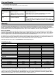
Warranty

A
B
D
C
E
G
F
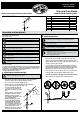
Item #1001 492 859
Model #HD28936
Use and Care Guide
LOW VOLTAGE FLOOD LIGHT
Part Description Quantity
A
Hood
1
B
Lens cover
1
C
20W MR11 Halogen Bi-Pin Bulb
1
D
Body
1
E
Adjustment screw
1
F
Post
1
G
Spike
1
H
Connector
1
PACKAGE CONTENTS
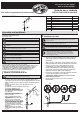
Assembly and Installation
1
Attaching and installing the light
2
Connecting the wires
WARNING: Never push the xture into the ground by the lamp body (D) or use a
hammer to insert the spike (G) into the ground.
WARNING: The wire connector (H) contacts have sharp edges for piercing the
main low voltage cable. To avoid injury, do not touch the metal contacts.
CAUTION: The wire from the low voltage power unit shall be 12-16 AWG type
underground low Energy Circuit Cable or SPT2W.
CAUTION: Safe for outdoor operation
WARNING: To reduce the risk of FIRE OR INJURY TO PERSONS:
WARNING: Turn off/unplug and allow to cool before replacing lamp.
WARNING: Lamp gets HOT quickly! Contact only switch/plug when turning on.
Do not touch hot lens, guard or enclosure.
WARNING: Keep the lamp away from materials that may burn.
WARNING: Do not touch the lamp at any time. Use a soft cloth. Oil from skin may
damage the lamp.
WARNING: Do not operate the luminaire tting with a missing or damaged lens
or bulb protector.
IMPORTANT:
• Protect the wiring by routing it in close proximity to the light tting, or next to a
building structure such as a house or deck.
• The landscape wire and connector can also be hidden under stone or buried
under grass at a maximum depth of 6” (15.24 cm).
• Do not submerge xture in water.
□ Carefully remove the xture from its protective packaging.
□ Run the wire through the notch in the top of the spike (G) and
attach the spike to the post (F) by turning clockwise.
□ Loosen set screw and slide off light cap (A).
□ Remove the lens cover (B) by turning counterclockwise.
□ Do not remove the lens from the lens cover.
□ Insert the bulb (C) into the bulb
socket. Use a soft cloth, as oil
from skin may damage the lamp
bulb.
□ Replace the lens cover (B) on the
body (D) by turning clockwise.
□ Adjust the xture’s angle by
loosening the adjustment screw
(E) and retightening it.
□ Replace the light cap (A) over
the body (D). Adjust the light’s
beam by sliding the cap back
and forth (back = wide beam,
front = narrow beam) and screw
the set screw in place once the
proper light beam is found.
□ NOTE: Ensure the lens points up
and never towards the ground.
WARNING: Risk of Electric Shock. Install all luminaires 10 ft. (3.05 m) or more
from a pool, spa or fountain.
WARNING: Install in accordance with all local codes and ordinances.
□ Place the wire connector (H) on opposite sides of the low
voltage cable (not included) where the xture will be located.
□ Align and t the main low voltage cable vertically to the slot of
the wire connector (H) as shown.
□ Press the wire connector (H) together until fully seated and
locked around the cable. Pre-set prongs will pierce the cable
insulation and establish contact. Turn on the power unit. If the
light xture does not turn on, repeat the previous steps.
□ Once the clip-on connector (H) is in place, it is recommended
to wrap it with electrical tape for additional protection.
□ CAUTION BE CAREFUL! THE WIRE STABS ARE VERY SHARP!
□ After all xtures are installed, turn on the transformer.
H
Only for use with low voltage power units with a maximum output rating of 15V,
300W per secondary.
FOR LANDSCAPE LIGHTING SYSTEMS ONLY. OUTDOOR USE ONLY. THE DEVICE IS
ACCEPTED AS A COMPONENT OF A LANDSCAPE LIGHTING SYSTEM WHERE THE
SUITABILITY OF THE COMBINATION SHALL BE DETERMINED BY CSA OR LOCAL
INSPECTION AUTHORITIES HAVING JURISDICTIO
N.
UL LISTED UNDER MODEL # U201167
Please read and save these instructions
INSTRUCTIONS PERTAINING TO A RISK OF FIRE, OR INJURY TO PERSONS
IMPORTANT SAFETY INSTRUCTIONS
Lighted lamp is HOT!
A
B
D
C
E
G
F
H
Set screw