C1000 by Prism Medical Introduction ................................................................... 2 Overview ....................................................................... 2 Components of lift system ............................................. 3 Component List ............................................................. 4 Specifications ................................................................ 4 Cautions ........................................................................
CAUTION: DO NOT ATTEMPT TO USE THIS EQUIPMENT WITHOUT FIRST UNDERSTANDING THE CONTENTS OF THIS MANUAL. Introduction Before using this equipment, and to ensure the safe operation of your C1000 lift, carefully read this entire manual, especially the section on “Cautions”. The C1000 is designed to be used in conjunction with Prism Medical lift track, accessories and slings. Please refer to any user guides supplied with these components and refer to them while reviewing this manual.
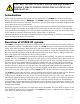
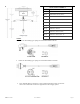
Components of lift system CHARGER BAT H BAT H BAT HROOM LIFT BED CHARGER LIFT TRACK BAT HROOM BED TRACK BEDROOM BEDROOM Figure 1A - Sample floor plan showing basic components of a ceiling lift system. Figure 1B - Alternate sample floor plan showing basic components of a ceiling lift system. Track Emergency Stop/ Lowering Carry bar Figure 2B - The C1000 ceiling lift with standard Emergency Stop/ Lowering.
Component List The following components are included with your new C1000 lift system: • • • • • C1000 lift (Manual or Motorized traverse) Pneumatic Hand Control Lift Charger (mounted on the wall or ceiling at the end of the track) Owner’s Manual Warranty Card SLINGS: If a sling has been supplied with the lift refer to the instructions included with the sling.
Models Table for C1000 Lift Lifting Range Code Description 329100 C1000 Manual Traverse 329101 C1000 Manual Traverse (Omni) 329102 C1000 Manual Traverse (Rev. G) 329103 C1000 lbs. Manual Traverse (Rev.A) 329126 C1000 Power RTC 329137 C1000 Power XY Traverse 329150 C1000 Power Traverse 329151 C1000 Power Traverse (Omni) 329152 C1000 Power Traverse (Rev. G) 329153 C1000 lbs. Power Traverse (Rev.
Cautions ● The C1000 must be installed prior to use. Contact your local authorized dealer to ensure that it is properly installed. The C1000 must be installed only by persons authorized by Prism Medical Ltd. ● Under no circumstance should the C1000 track, lift and sling (s) or entire system be put in control of a person who has not been properly trained in the use and care of this equipment.
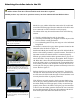
Attaching the airline tube to the lift Caution: A sturdy ladder may be required in order to access the underside of the lift to re-attach the rubber airline of the lift. Caution should be used when this is required. Should you have any concerns or questions contact your local authorized Prism Medical dealer. Should the gray rubber airline that connects the lift to the hand control become disengaged from the underside of the lift it must be re-connected in order for the lift to work properly.
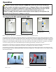
Operation Caution: Always, before using the C1000 lift system, the lift, track and sling (s) must be visually checked for any unusual wear, or damage. Refer to the user manual with each piece of supplied equipment to determine what should be checked. Should anything look unusual contact your local Prism Medical dealer prior to use. Failure to comply with this caution could result in serious injury to the operator, the individual being lifted and/or damage to the lift.
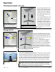
Operation Raising/lowering the carry bar By pressing the DOWN arrow button, or the UP arrow button, the carry bar can be lowered/ raised to the correct height for attaching the sling or positioning an individual. Refer to figure 5A and 5B UP DOWN Figure 5A - Power traverse hand control showing raising/lowering functions Figure 5B - Lift showing raising/lowering of carry bar.
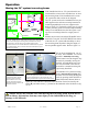
Operation Moving the “H” system traversing beam TRAV E RS ING BE AM BAT H BED BAT HROOM The “H” system involves the installation of two parallel support tracks and one traversing beam that is mounted perpendicular to the two support tracks. Refer to figure 7A. The benefit of this type of system is that it provides greater movement and positioning ability for an individual since the floor space coverage area is much larger than for a single piece of track.
Attaching the carry bar to the lift Latch Open the Latch Quick Release Carabiner Dowel Pin Figure 8A - Open the latch of Quick Release Carabiner Figure 8B - Insert the Dowel Pin of carry bar into the hook of Quick Release Carabiner Your lift has come with a Quick Release Carabiner on the strap. Open the latch of Quick Release Carabiner by hand. Refer to figure 8A. Insert the Dowel Pin of carry bar into the hook of Quick Release Carabiner and release the latch.
Return To Charge (If Equipped) If your motorized, traversing lift has a return-to-charge feature (RTC), pressing & holding the blue and yellow colored directional hand control buttons simultaneously for 3-5 seconds (to produce beeping noise) will automatically retract the lift’s carry bar and drive the lift along its track until it docks at the charger. Figure 8D - Press & Hold the blue and yellow color hand control buttons simultaneously to activate the RTC feature.
Basics in transferring an individual Caution: The following steps are intended to generally illustrate the procedure involved in the lifting and transferring of an individual from one location to another using the lift, track and sling. Track configurations will vary by installation. The manual for the sling that was purchased with the lift should be reviewed in detail prior to attempting these steps, as the sling illustrated here may not be the same as the one that was purchased.
Basics in transferring an individual … continued Step 6) Once at the correct height the individual can be moved along the track to the desired location. Refer to the sections already described in this manual on how to move the lift along the track Step 7) Once at the desired location the individual in the sling can be lowered/raised to the correct height in order to complete the transfer.
C1000 TANDEM BARIATRIC SYSTEM In cases where a client’s weight, size or medical condition requires precise control when transferring or re-positioning, The C-1000 Tandem Bariatric Lift provides a safe and reliable solution. The transfer or re-positioning of Bariatric clients can be difficult. A single track can push the legs of a Bariatric client toward the torso, decreasing the hip angle, and compressing the upper body. This can cause discomfort and, in some cases compromise breathing.
C1000 TANDEM BARIATRIC SYSTEM CARRY BAR ACCESSORY Tandem Bariatric System Carry Bar allows users to take full advantage of dual motor positioning giving greater control of a client’s weight between the two (torso and leg) lifting motors. The part number for the Tandem Bariatric Carry Bar is 360765.
Charging the lift The charger contacts with two metal charging strips that run along the inside of the track. Whenever the lift is over a section of track with charging strips it will automatically start to charge the lift if its battery is low. The batteries should be charged on a regular basis. It is recommended that the lift be left on charge when not in operation, and at the end of each day.
After one hour, the lift may be used, however, overnight charging is recommended. The EMERGENCY DOWN function along with XY TRAVERSING will continue to operate. In addition to the indicator lights on the lift, the charger has an indicator light. When ORANGE, it indicates that the batteries are low and being charged. Refer to figure 11A. Figure 11A - Charger close-up showing charging indicator light is ORANGE indicating that the lift is connected and is charging.
LCD Display Functionality Default Display Modes: The lift unit can be set to either of the following as the ‘Default’ display mode: 1. Battery Level (the factory setting for the Default Display Mode); or, 2. Number of Lifts. To change from one operating mode to another please call your local service technician. In Battery Level Mode the lift will: 1. Display the word, “Battery”, with the percentage charged (in 10% increments) in the top row of the display (e.g., “Battery Level 60%”). 2.
LCD Display Functionality In any ‘Default display mode’, if the unit is in the charger the lift will go into Charging Display Mode regardless what the user has selected as ‘Default Display Mode’. Charging Display Mode will over-ride Low Battery Mode. The lift will then: 7. Display a flashing “Charging” with the percentage charged (in 10% increments) in the top row of the display (e.g., “Charging 60%”). 8.
Emergency Stopping Pull Down Once The lift unit also has an Emergency Shut-off feature that allows the operator to shut the power to the lift unit completely off. By pulling down once on the RED emergency lowering cord, located on the underside of the lift unit, the lift will immediately stop and all its functions will be disabled. The unit will beep once and all power to the lift will be turned off.
Emergency Manual Raising or Lowering Caution: The manual emergency raising and lowering system should be used only if the lowering procedures described in the previous section of the manual do not work, or, if the emergency raising function is required. Should you have any concerns or questions contact your local authorized Prism Medical dealer. Caution: A proper safety ladder or stool may be required in order to remove the cover of the device. Use extreme caution if this is required.
Cleaning and Disinfection The exterior of the lift should only be cleaned, disinfected using isopropyl alcohol. Damp a cloth with isopropyl alcohol and wipe down entire exterior of lift and hook. No other chemicals and/or liquids should be used to clean, disinfect and sterilize this lift. Caution: Take great care to ensure that no liquids get inside the lift. This lift is not drip proof or water tight.
Trouble Shooting Should problems arise with the use of the lift review the following chart. Find the fault and complete the recommended solution. If the fault is not found and/or the solution does not correct the problem contact your local Waverley authorized dealer for service immediately. Fault Recommended Solution The airline tubing that connects the hand control to the lift has become disengaged. Refer to the section of this manual titled “Attaching the airline tube to the lift”.
General Inspection and Maintenance A) Each Use - To be completed by User Prior to each use the C1000 lift and associated track, accessories and sling (s), must be visually inspected. Refer to the accessory and sling user guides for specific details regarding their inspection. Should any of the these items fail the inspection do not use the lift Contact your local authorized dealer for service.
Lift Accessories The following is a list of available accessories for the C1000 lift. Items such as the track, turntables and brackets are installed at the time of purchase. Add-on pieces are available to after the initial purchase, however your local authorized dealer must be consulted as to suitability, purchase and installation. Slings are the most common after purchase accessory. A variety of styles, sizes, and colors are available. Custom slings can also be manufactured to meet special needs.
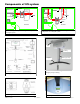
Service Record History - Initial Information Complete the following section on Purchase and Service Information as soon as this equipment is installed. Use the service record history to record to any completed service and repairs. Ensure that the service record is signed and dated each time it is used. Be sure to have this piece of equipment serviced on a regular basis as described in the General Inspection and Maintenance Section.
Service Record History Date: _______________________ Service Type: □ Periodic Inspection □ Monthly Inspection Completed By: _________________________ Complete this section after each service, repair inspection and/ or maintenance. Photocopy additional pages as required.
Service Record History Date: _______________________ Complete this section after each service, repair inspection and/ or maintenance. Photocopy additional pages as required.
Service Record History Date: _______________________ Service Type: □ Periodic Inspection □ Monthly Inspection Completed By: _________________________ Complete this section after each service, repair inspection and/ or maintenance. Photocopy additional pages as required.
Warranty This Warranty does not affect or in any way limit your Statutory Rights 1) Subject to the exclusions set out in Clause 2, the conditions set out in Clause 3 and the limitations set out in Clause 4, Prism Medical, as sole licensed representative of Corven Healthcare Inc., guarantees all equipment supplied as new against failure within the period of 1 year from date of purchase by virtue of defects in material or workmanship.