
Product Manual

C1000 - User Guide Rev: 9SEP2011 Page: 10
Operation
Moving the “H” system traversing beam
If the installed track is an “H” system then this sec-
tion should be reviewed as it describes how to move
the traversing beam. If the installed track is not an
“H” system then this section can be skipped.
The “H” system involves the installation of two par-
allel support tracks and one traversing beam that is
mounted perpendicular to the two support tracks.
Refer to figure 7A. The benefit of this type of system
is that it provides greater movement and positioning
ability for an individual since the floor space cover-
age area is much larger than for a single piece of
track.
Besides the previously described UP/DOWN move-
ment of the carry bar, and LEFT/RIGHT movement
of the lift, the “H” system adds the ability to move
the traversing beam anywhere along the length of
the two parallel support tracks. Refer to figure 7A.
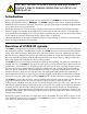
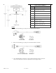
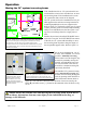
Figure 7A - Sample of “H” system room covering layout. Note that the
lift can be moved along the traversing beam, and that the traversing
beam itself can be moved along the two parallel support tracks.
The actual direction of travel when the hand control buttons are pressed
may be different than shown, since the track and lift orientation may be
different than installed. .
BATHROOM
BEDROOM
BED
SUPPORT
TRACK
(BOTH SIDES)
BATH
TR AV E RS IN G
BE AM
LIFT
CHARGING
LOCATION
CHARGER
This can be accomplished in one of
two ways. If the installed “H” travers-
ing beam is manually traversing
then the beam is moved along the sup-
port tracks by manually moving the
beam, lift, and individual in one mo-
tion. This movement is the same as
that used for a manual traversing lift,
as previously described.
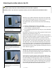
If the installed “H” system traversing
beam is motorized traversing then
the beam is moved along the support
tracks by pressing either the black or
white hand control button. Refer to
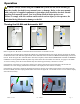
figure 7B. This will move the beam in the direction of travel as noted by the
black [▼] and white arrows [▲]located on the underside of the lift. Refer to fig-
ure 7C.
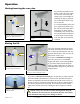
Figure 7C - Directional arrows on underside of power
traverse “H” system lift. Black and white arrows show
traversing beam direction of travel when the corre-
sponding colored button is pressed on the hand control.
Figure 7B - Power traverse “H”
system hand control showing
traversing beam movement
buttons. Button colors corre-
spond to the black and white
directional arrows located on the
underside of the lift.
Caution: Always use extreme care when moving the traversing beam. Watch out for
and avoid any obstructions that may cause injury to the individual in the sling, or
damage to the lift/track.