
Product manual

Page 8 For technical questions, please call 1-888-866-5797. Item 61256
SAFETY OPERATION MAINTENANCESETUP
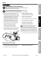
Installation and Setup
Read the ENTIRE IMPORTANT SAFETY INFORMATION section at the beginning of this
manual including all text under subheadings therein before set up or use of this product.
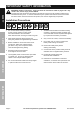
Mounting the Winch
1. The mounting plate must be rated to
at least the winch’s capacity.
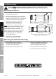
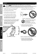
2. Align the winch perpendicular to center line of
the vehicle at the desired location, and mark the
locations of the winch base holes. Compare the
dimensions of the marked holes to Figure D.
3. Before drilling, verify that the installation
surface has no hidden components or
structural pieces that will be damaged.
NOTE: This winch can generate extreme forces.
Select a location that can withstand the rated
capacity without damage or weakening. Steel
reinforcement plates may be needed or a
certified welder may need to weld on additional
bracing depending on the mounting location.
4. Drill holes appropriate for the hardware
at the marked locations.
5. Install the winch using the hardware
specified on the specification chart.
10 in. / 254.6mm
20.94 in. / 532mm
4*Ø0.43 in. / 11mm
6.3 in. / 160mm
4.49 in.
/ 114mm
8.8 in. / 223.6mm 5.28 in. / 134mm6.85 in. / 174mm
8.58 in. / 218mm
Figure D: Winch Dimensions
Mounting the Solenoid Assembly
1. Place the Solenoid Box in a suitable
place near enough to the winch to allow
the cables to be routed properly.
2. Mark the where the screw holes will be.
3. Verify that the installation surface has no
hidden components or structural pieces
that will be damaged before drilling.
4. Drill pilot holes for the mounting screws.
5. Secure in place with mounting screws.