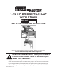
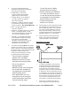
-1/2 HP BRIDGE TILE SAW WITH STAND Model 97360 SET UP AND OPERATING INSTRUCTIONS Please Note: Diamond Blade not included, sold separately. Wheels not shown on Stand. Visit our website at: http://www.harborfreight.com Read this material before using this product. Failure to do so can result in serious injury. SAVE THIS MANUAL. Copyright© 2007 by Harbor Freight Tools®. All rights reserved.
CAUTION, without the safety alert symbol, is used to address practices not related to personal injury. SAVE THIS MANUAL Keep this manual for the safety warnings and precautions, assembly, operating, inspection, maintenance and cleaning procedures. Write the product’s serial number in the back of the manual near the assembly diagram (or month and year of purchase if product has no number). Keep this manual and the receipt in a safe and dry place for future reference.
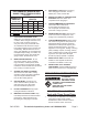
RECOMMENDED MINIMUM WIRE GAUGE FOR EXTENSION CORDS (120 VOLT) NAMEPLATE AMPERES (at full load) EXTENSION CORD LENGTH 25’ 50’ 100’ 150’ 0–6 18 16 16 14 6.1 – 10 18 16 14 12 10.1 – 12 16 16 14 12 12.1 – 16 14 12 10. 11. USE PROPER EXTENSION CORD. Make sure your extension cord is in good condition. When using an extension cord, be sure to use one heavy enough to carry the current your product will draw.
equipped with an electric cord having an equipment-grounding conductor and a grounding plug. The plug must be plugged into a matching outlet that is properly installed and grounded in accordance with all local codes and ordinances. 2. Do not modify the plug provided – if it will not fit the outlet, have the proper outlet installed by a qualified electrician. 3. Improper connection of the equipmentgrounding conductor can result in a risk of electric shock.
8. Correct the cause of blade binding before proceeding. To properly understand all safety warnings, be familiar with the following safety terms and equipment: • Before continuing an unfinished cut, center the blade in the precut kerf and check that the saw is not engaged into the workpiece before turning on the saw. a. Featherboard – A block with “fingers” that hold the workpiece against the fence while sawing. b.
fuse or circuit breaker that supplies power to the tool. Then unplug and examine for presence of water in the receptacle. 10. Industrial applications must follow OSHA guidelines. 11. Maintain labels and nameplates on the tool. These carry important safety information. If unreadable or missing, contact Harbor Freight Tools for a replacement. 12. Avoid unintentional starting. Prepare to begin work before turning on the tool. 13. People with pacemakers should consult their physician(s) before use.
Vibration Safety This tool vibrates during use. Repeated or long-term exposure to vibration may cause temporary or permanent physical injury, particularly to the hands, arms and shoulders. To reduce the risk of vibration-related injury: 1. Anyone using vibrating tools regularly or for an extended period should first be examined by a doctor and then have regular medical check-ups to ensure medical problems are not being caused or worsened from use.
TO PREVENT SERIOUS INJURY FROM ACCIDENTAL SPECIFICATIONS Electrical Requirements 120 V~ / 60 Hz / 9.2 A Motor Speed 3550 RPM 7" Diameter / Continuous Rim Blade Rated at 3550 Blade Diameter RPM or Greater (Diamond Blade (SKU 67111 Diamond Sold Separately) Wet Blade available from Harbor Freight Tools) Maximum Cutting 1” @ 45° Capacity 1” @ 90° Floor and Wall Tiles: 24” x 24” Maximum Tile Size Marble and Brick: 25” long 0° to 45° in 2.
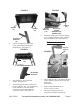
FIGURE 3 FIGURE 5 STAND II (64) MOTOR SUPPORT (111) STAND I (57) 5. SUPPORT BRACKET (58) 2. HANDLE (38) BOLTS (98), SPRING WASHERS (95), WASHERS (94) Attach the Handle (38) to the Motor Support (111), using the Bolts (98), Spring Washers (95), and Washers (94). (See Figure 5.) To Attach the Knobs: Pull out the Stand I (57) and Stand II (64), fully extending the Support Brackets (58). (See Figure 3.
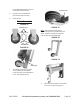
in the Right Rail Stand (41) and into the threaded hole as shown. 4. Repeat for the Left Rail Stand (24) and the other Knob (22). 5. Secure Knobs. Hex Nuts (123) Wheel Assembly FIGURE 7A FIGURE 7C Washers (121) Note: Bolts should be inserted from outside, through the leg stand and into the wheel. Washers and Nuts to be placed onto the Bolts from the wheel side. Hex Nuts (123) FIGURE 7D Bolts (120) Wheels (126) FIGURE 7B FIGURE 7E Stand II (64) 1.
OPERATING INSTRUCTIONS Read the ENTIRE IMPORTANT SAFETY INFORMATION section at the beginning of this manual including all text under subheadings therein before set up or use of this product. Tool Set Up TO PREVENT SERIOUS INJURY FROM ACCIDENTAL OPERATION: Turn the Power Switch of the tool to its “OFF” position and unplug the tool from its electrical outlet before performing any inspection, maintenance, or cleaning procedures.
Positioning the Tile POSITION OF TILE CIRCUIT BREAKER (32) TABLE (44) SCALE RAIL (49) ANGLE CUTTING GUIDE (46) BUTTERFLY KNOB (47) FIGURE 10 1. POWER SWITCH (37) FIGURE 11 6. Loosen the T-Knob (47) on the Angle Cutting Guide (46) and position at 90 degrees on the Scale Rail (49). Then, retighten the T-Knob. (See Figure 10.) 2. To Adjust the gap between the Angle Cutting Guide (46) and the cutting slot in the Table (44), loosen the Butterfly Knob (47) on the Scale Rail (49).
Breaker by pushing in the button. Then, turn the Power Switch to its “ON” position to resume cutting. (See Figure 11.) To Make A Bevel Cut; RIGHT END Note: If the Pump fails, first try clearing the Filter of debris and make sure it is not plugged. If Pump still does not operate properly, it must be replaced. To Make A Miter Cut: KNOB (22) ANGLE CUTTING GUIDE (46) SCALE RAIL (49) 45° ANGLE CUTTING GUIDE (65) LEFT END KNOB (22) BUTTERFLY KNOB (47) FIGURE 13 1. 2. 3.
the other Wrench (70) provided, unscrew and remove the Nut (6) by turning it clockwise. Next, remove the Outside Flange (5) and remove told Blade. (See Figures 16 and 17.) To Change The Saw Blade: WARNING! Make sure the Power Switch (37) of the Tile Saw is in its “OFF” position and that the unit is unplugged from its electrical outlet before performing this procedure.
FIGURE 19 SAW BLADE (4) ARROW BOLT (91) SPRING WASHER (89) WASHER (88) 8. BOLT (91) SPRING WASHER (89) WASHER (88) Carefully lower Blade Guard (12) back into its original position. Then secure Blade Guard in place using the Bolts (91), Spring Washers (89), and Washers (88). (See Figure 19.) SAW BLADE (12) ARROW FIGURE 18 6. IMPORTANT: When installing a Saw Blade (4), make sure the “ARROW” depicted on the side of the Saw Blade points in the same direction as that of the Blade Guard (12).
MAINTENANCE AND SERVICING Procedures not specifically explained in this manual must be performed only by a qualified technician. TO PREVENT SERIOUS INJURY FROM ACCIDENTAL OPERATION: Turn the Power Switch of the tool to its “OFF” position and unplug the tool from its electrical outlet before performing any inspection, maintenance, or cleaning procedures. TO PREVENT SERIOUS INJURY FROM TOOL FAILURE: Do not use damaged equipment.
Troubleshooting Problem 1. Tool will not start 2. 1. Blade spins slowly 2. Excessive vibration 1. 2. Running hot; 1. excess smoke 2. 3. Possible Causes No power at outlet. Cord not connected. Arbor shaft binding Motor brushes worn Bent or off-balance blade Bent Arbor Shaft Water flow problem. Not enough water Running with hot/warm water 1. 2. 1. 2. 1. 2. 1. 2. 3. Likely Solutions Check power at outlet. Check that cord is plugged in.
PARTS LIST 1 Motor 33 Capacitor Fixture 68 Pump Fixture 104 Hex Nut 2 Motor Cover 34 Capacitor 69 Drain Plug 105 Hex Bolts 3 Inside Flange B 35 Switch Box 70 Wrench 106 Nut 4 Saw Blade (not included) 36 Capacitor Spacer 71 Wrench 107 Hex Nut 5 Outside Flange 37 Power Switch 72 Hex Nut 108 Washer A 6 Hex Nut 38 Handle 73 Washer A 109 Bolt 39 Handle Grip 74 Lock Washer 110 Control Box Seal 40 Right Spacer 75 Hex Bolts 111 Motor Support 41 Right Rai
ASSembly DIAgrAm 140 ASSEMBLY DIAGRAM Please Note: Saw Blade (4) is sold separately and not included. Rev 09j SKU 97360 For technical questions, please call 1-800-444-3353.
LIMITED 90 DAY WARRANTY Harbor Freight Tools Co. makes every effort to assure that its products meet high quality and durability standards, and warrants to the original purchaser that this product is free from defects in materials and workmanship for the period of 90 days from the date of purchase.