
Owner's Manual

Page 10SKU 97360 For technical questions, please call 1-800-444-3353.
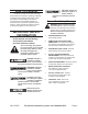
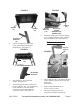
in the Right Rail Stand (41) and into
the threaded hole as shown.
4. Repeat for the Left Rail Stand
(24) and the other Knob (22).
5. Secure Knobs.
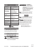
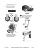
Wheel Assembly
1.
FIGURE 7A
Washers (121)
Wheels (126)
Bolts (120)
Hex Nuts (123)
FIGURE 7B
Stand II (64)
The Wheels (126) are connected
to the Stand II (64) using Bolts
(120), Hex Nuts (123) and Washers
(121). (See Figures 7A-7E)
FIGURE 7C
Hex Nuts (123)
Note: Bolts should be inserted from
outside, through the leg stand and into the
wheel. Washers and Nuts to be placed
onto the Bolts from the wheel side.
2.
FIGURE 7E
FIGURE 7D
Lift the saw stand with the front handle
to move it, as shown in gure 7E.