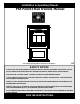
Installation & Operating Manual P68 Pellet Stove Owners Manual R3 “Ce manuel est disponible en Français sur demande” SAFETY NOTICE PLEASE READ THIS ENTIRE MANUAL BEFORE YOU INSTALL AND USE YOUR NEW ROOM HEATER. FAILURE TO FOLLOW INSTRUCTIONS MAY RESULT IN PROPERTY DAMAGE, BODILY INJURY, OR EVEN DEATH. FOR USE IN THE U.S. AND CANADA. SUITABLE FOR INSTALLATION IN MOBILE HOMES. IF THIS HARMAN STOVE IS NOT PROPERLY INSTALLED, A HOUSE FIRE MAY RESULT. FOR YOUR SAFETY, FOLLOW INSTALLATION DIRECTIONS.
P68 Pellet Stove
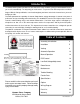
Introduction The Award-Winning P68 Pellet Stove has the widest BTU range available, giving you 0 to 68,000 BTU when you need it, automatically. The only thing you need to do is set your desired room temperature and fill the hopper. With the P68 you will notice even heat throughout your home and a level of convenience you never thought possible. The P68 epitomizes the capability of Harman Pellet Stoves, taking advantage of Harman’s 20 years of pellet stove design, technology and manufacturing.
IMPORTANT NOTES DO NOT INSTALL A FLUE DAMPER IN THE EXHAUST VENTING SYSTEM OF THIS UNIT. DO NOT CONNECT THIS UNIT TO A CHIMNEY FLUE SERVING ANOTHER APPLIANCE. Mobile home installation should be done in accordance with the Manufactured Home and Safety Standard (HUD), CFR 3280, Part 24. 4 P68 Pellet Stove WARNING DO NOT INSTALL IN SLEEPING ROOM CAUTION THE STRUCTURAL INTEGRITY OF THE MOBILE HOME FLOOR, WALL, AND CEILING/ROOF MUST BE MAINTAINED.
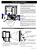
Assembly and Installation Unpacking The P68 is bolted (1/4 x 1" hex head bolts) to the skid to prevent movement during shipping. To free the stove from the skid you must remove the hold-down bolts in the rear of the pedestal base. Installing rear cover panels The rear cover panels are removed from the stove to make it easier to get at the hold-down bolts. The rear cover panels are packed inside the hopper and should be installed on the stove as shown.
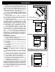
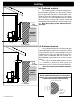
Installation 6 P68 Pellet Stove 9"-13" 9"-13" 9" With Side Shields 13" Without Side Shields Fig. 3 2" 14" Fig. 4 2" 20" Fig. 5 Floor Protection must be 2 inches to each side, 6 inches to the front, and 0 inches to the back of the stove. Floor Protector minimum: 25" wide x 33" deep.
Venting Requirements for Terminating the Venting WARNING: Venting terminals must not be recessed into a wall or siding. NOTE: Only PL vent pipe wall pass-throughs and fire stops should be used when venting through combustible materials. NOTE: Always take into consideration the effects of the prevailing wind direction or other wind currents that may cause flyash and/or smoke when placing the termination vent. In addition, the following must be observed: A. The clearance above grade must be a minimum of 18".
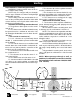
Venting IMPORTANT NOTICE Pellet Vent Pipe or PL Vent Pipe Must Be Used. + + + - = Positive Static Pressure = Negative Static Pressure Fig. 7 Venting A combustion blower is used to extract the combustion gases from the firebox. This causes a negative pressure in the firebox and a positive pressure in the venting system as shown in Fig. 7. The longer the vent pipe and more elbows used in the system, the greater the flow resistance.
Venting Outside Air Here are four benefits of outside air: Outside air flex pipe goes here. 1. Having air introduced from outside the living area boosts overall efficiency. 2. It eliminates draft problems that can occur in tight homes. 3. It reduces smoke spillage in the event of a power failure. Flex pipe part# 2-00-08543 (3') 1-00-08543 (25') Inlet Cover part# 1-10-08542 4. It allows your vent termination to be as close as 18" from windows or doors.
Venting #1 Preferred method This method provides excellent venting for normal operation and allows the stove to be installed closest to the wall. Two inches from the wall is safe; however, four inches allows better access to remove the rear panel. The vertical portion of the vent should be three to five feet high. This vertical section will help provide natural draft in the event of a power failure. Note: Do not place joints within wall pass3 ft. to combustibles throughs. Combustibles allowed beyond 3 ft.
Venting #4 Installing into an existing chimney ( US only ) This method provides excellent venting for normal operation. This method also provides natural draft in the event of a power failure. If the chimney condition is questionable* you may want to install a liner as in method #7. *The chimney should be inspected and cleaned before installing your stove.
Venting #6 Installing into an existing fireplace chimney ( US and Canada) This method provides excellent venting for normal operation. This method also provides natural draft in the event of a power failure. In Canada and some places in the US it is required that the vent pipe extend all the way to the top of the chimney. In this method a cap should also be installed on the chimney to keep out rain. Be sure to use approved pellet vent pipe fittings.
Venting 12" min. Storm collar Flashing 3" min. 3" min. PL vent manufacturer's fi re stop s pa ce r an d support 3" min. No ins ulation or other combustible ma te ri al s are allowed within 3" of the PL vent pipe. Minimum flue vent configuration It is recommended that outside air be installed with this venting configuration to reduce smoke and creosote smell in the room in the event of power failure. (See Page 5 for corner installation clearances) 18" Fig.
P68 AUTOMATIC IGNITION/OPERATION The P68 is a fully automatic stove that features two operating modes; Stove Temperature Mode and Room Temperature Mode. In Stove Temperature Mode, you select a burn rate and the stove will remain at the same burn rate regardless of the room temperature.
P68 AUTOMATIC IGNITION/OPERATION Stove Temperature Mode Shut Down Procedure In the Stove Temperature Mode and with the igniter toggle switch in the Auto position, the stove will light automatically and can be adjusted to the desired setting using the same temperature control dial as is used in the Room Temperature Mode. The heat output and fuel consumption will remain constant regardless of room temperature.
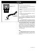
P68 AUTOMATIC START UP Starting First Fire Igniter Switch to"AUTO"(up position) Make sure the unit is plugged into a 120 VAC, 60 HZ electrical source. The power light should be the only light lit. Fig. 17 Flame Guide See Note 7. 1" NOTICE: When power is given to the stove, the control board will blink a few times to indicate current version of control board. 1. Turn Mode Selector to "OFF". 2. Fill hopper with pellets.1 3. Clean burn pot with scraper, if necessary.5 Fig. 18 Helpful Hints 1.
P68 MANUAL IGNITION/OPERATION The P68 Pellet Stove is capable of manual operation. This also allows the operator to manually control operation during an emergency (i.e. igniter failure, when using a 502H battery backup, or when using certain generators.) The unit can be switched between "AUTO" and "MANUAL" at any time during operation.
P68 MANUAL START UP Starting First Fire Fig. 20 Fig. 19 See Note 7. 1" Igniter Switch to"MANUAL" (down position) Make sure the unit is plugged into a 120 VAC, 60 HZ electrical source. The power light should be the only light lit. 1. Turn FEED ADJUSTER to desired feed rate. No. 4 is good for most pellets.4 2. Turn the MODE SELECTOR to “OFF” and then to the desired mode. This will reset control and start the combustion motor. 3. Turn the TEMPERATURE DIAL to the desired setting. 4.
P68 AUTOMATIC IGNITION ESP CONTROL Power Light Indicates power to the control. Feed adjuster Sets the maximum feed rate Status Light Will be lit in either stove or room temp mode when pointer is not within off position band except after normal shut down. Blinks to indicate errors listed below. Test Runs all motors at full speed for one minute to check operation.
P68 Low Draft Voltage Adjustment Co mb us ti on Motor Speed Control Low draft only set point. The small straight screwdriver slot is plastic; therefore, the unit can be adjusted while in operation. Fig.22 Draft Meter bolt hole location On a P68 the draft test hole is under the left rear corner of the firebox. Fig. 23 Fig.1 Low Draft Voltage Adjustment These units are pre-tested at the factory with exactly 120 Volts A.C., 60 Hz.
Room Sensor and Rear Shield Installation Rear Shields Room Sensor Installation Room Sensor Port 5/16" Hex Head Screws (3 on each side) 5/16" Hex Head Screws (3 on each side) Fig. 24 The room sensor is a small temperature sensor on the end of a 60" gray wire. This sensor is installed much like a standard wall thermostat. Because it is so small, it can be hidden along the trim of a doorway or even up the leg of a coffee table.
Maintenance Cleaning the Door Glass • Always use a soft cloth and glass cleaner (such as Windex, or a mixture of vinegar & water) to clean the glass. • Do not use razor blades or any other hard object to scrape the glass. Removing Ashes: When approximately 1 ton of pellets has been burned it will be necessary to empty the ash pan. Combustion Blower Cover Fig 26 Ashes should be placed in a metal container with a tight fitting lid.
Maintenance Clean-out plate Fig. 28 Latch "closed "with blower cover in place. Burn pot clean-out is closed. Fig. 29 Latch "open "with blower cover partly removed. Burn pot clean-out is open. 8. Clean the combustion blower wheel with a brush and a vacuum cleaner. Note: Do not use a household vacuum to clean the stove. We recommend that you use a shop vacuum that is equipped with a fine dust filter called a HEPA filter or a vacuum specially made for fly ash and soot.
P68 Maintenance - Burn Pot Burn Pot Cleaning and Maintenance 1. Scrape the top holed surface and sides of the burn pot.(Fig 34) It is not necessary to completely remove all material from the burn pot. The excess will be pushed out during the next use. DANGER Disconnect the power to the unit before removing cover. 2. Loosen the (2) wing thumb screws on the lower front angle of the burn pot. (Fig. 34) 3. Lift off the clean-out cover (Fig.35) to open the bottom clean-out chamber. (Fig.36) 4.
P68 Maintenance - Gasket Adjustment Your new Harman Stove viewing door gasket has been factory set, however over a period of time some minor adjus tment may be necessar y. The easiest way to check the adjustment of the door gasket is to take a small piece of paper or a dollar bill (when the stove is not burning) and open the door, place the paper between the face of stove body and the gasket at the top center of the door, close the door.
P68 Maintenance - Cleaning the Feeder Body Pellet fines will accumulate in the feeder body over a period of time; therefore, a yearly inspection and cleaning of this must be performed. To clean out fines: 1. Remove right rear cover panel ( see rear cover installation on page 4 ). 2. Remove wing nut and feeder cover on the right side of the feeder. 3. Use a vacuum cleaner to remove all fines. 4. Reinstall feed cover, wing nut, and right rear cover panel.
P68 Trouble-Shooting FEEDER DOES NOT FEED 1. No pellets in hopper. 2. Firebox draft may be too low for low draft pressure switch in feeder circuit to operate. Check for closed doors, loose or missing gasket on doors or hopper lid, or a faulty pressure switch. 3. Feed motor will not run until ESP senses 165 deg. F. Maybe you did not put enough pellets in the burn pot before lighting the fire manually. 4. Something is restricting flow in the hopper or causing the slide plate to stick. 5.
P61A Feeder P68 Feeder and Specifications ( 4) 3- 30- 2252005013 3- 30- 1371612513 MOTOR BLADE 3- 20- 2046399 Specifications Weight Blower Feed Rate Hopper Capacity Fuel Flue Size Outside Air Size Fuse Rating 28 P68 Pellet Stove 290 lbs. 135 cfm approx. 1lb. to 8 lbs per hr 76 lbs Wood Pellets 3 inch 2 3/8" I.D.
OPTIONS Side Heat Shields Floor Protector Side heat shields are available to reduce the clearance to combustible materials. Part #1-00-06716 The P68 Steel Floor Protector measures 25 inches wide by 33 inches deep. It is made of 20 gauge steel. This is the minimum size for floor protection with this unit.
68 J2 6 P68 Wiring Diagram 30 P68 Pellet Stove
P68 Parts List Description Hopper Gasket(6 ft.
HARMAN GOLD WARRANTY 6 YEAR TRANSFERABLE LIMITED WARRANTY (Residential) 1 YEAR LIMITED WARRANTY (Commercial) Harman Stove Company warrants its products to be free from defects in material or workmanship, in normal use and service, for a period of 6 years from the date of sales invoice and for mechanical and electrical failures, in normal use and service, for a period of 3 years from the date of sales invoice.