HARRINGTON SIGNAL INC.
Copyrights and Trademarks The installer is to hand over this manual to the owner of the system upon completion of work. This manual is copyright 1994 - 2005 by Harrington Inc. No part of this publication may be reproduced, transmitted, transcribed, stored in a retrieval system, or translated into any language or computer language, in any form by any means electronic, magnetic, optical, chemical, manual, or otherwise without the prior consent of Harrington Inc. Harrington Signal, Inc. 2519 4th Ave.
HS-3100/3200 Operator’s Manual Contents 1.0 Unit Operation .......................................................................................................................................... 1.1 Power Up Sequence ....................................................................................................................... 1.2 Types of Inputs ............................................................................................................................... 1.3 Status Display ....
HS-3100/3200 Operator’s Manual ii
HS-3100/3200 Operator’s Manual 1.0 Unit Operation 1.1 Power Up Sequence The power up sequence of the HS-3100/3200 (hereafter referred to as the HS-3200) panel is started in the following ways: power is applied to the panel; the hard reboot button at the top of the main board is pressed; a Network Reboot command is issued; or the panel has a fault that triggers the internal watch-dog. The LCD will first display configuration information, then "INITIALIZING MEMORY PLEASE WAIT".
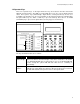
HS-3100/3200 Operator’s Manual 1.3 Status Display The status display is located in the middle of the main display. It consists of 8 LEDs. The alarm (red), supervisory (yellow), trouble (yellow), ground fault (yellow), and NAC trouble (yellow) LEDs will flash for any new condition and will be latched by the Acknowledge key. The AC LED (green) will be on while the panel has AC power applied to it. The monitor LED (green) will turn on if any monitor type input is active.
HS-3100/3200 Operator’s Manual 1.6 Operator Keys There are 8 operator keys. In the figure below, the keys are located on the lower left and are labelled “System Controls” The LEDs associated with these keys are used to display function status. The top three keys (Acknowledge, Signal Silence, and System Reset) are not userassignable. The bottom 5 keys are user-assignable for the functions listed in the following table.
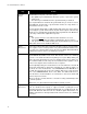
HS-3100/3200 Operator’s Manual Key System Reset Action System Reset resets part or all of the system. • • The rightmost green LED flashes when the system, or part of the system, can be reset. The leftmost green LED flashes if the ground fault relay is activated. Press System Reset to deactivate the ground fault relay to check for restores and additional ground faults. If ground faults remain, the relay will be reactivated after 5 to 30 seconds.
HS-3100/3200 Operator’s Manual Key Action Common Disconnect This function is configurable. It can be programmed to disable the relays or to disable a City Tie module (HS3CTYB). When an HS3CTYB module is disconnected, a trouble will be reported to the city and then any subsequent signals will not be reported until the card is re-enabled. When the relays are disabled, the yellow LED flashes while the relays are disabled. If no relays are selected for disabling, Common Disconnect is unavailable.
HS-3100/3200 Operator’s Manual the First or Last entry. Once viewing the events, one can look at the next one using the or the previous one with the . will act as either or , whichever was pressed last. and will rotate between pages of the event.
HS-3100/3200 Operator’s Manual The Main Menu has the following selections: Status: Displays the current status of various parts of the panel. The following options are available: More: Displays the next screen of menu options. When the last screen of the menu is displayed the next screen will be the first one again. Misc. Trouble: Displays any troubles with the bells, releasers, AC power, batteries, etc., that are not shown elsewhere. Only sections in trouble will be displayed.
HS-3100/3200 Operator’s Manual of occurrence for events occurring at or to the panel. There may be a second screen including information from the database. You can start by looking at either the last event (newest) or the first event (oldest). When viewing the events, scroll to the next one using the or the previous one with the . will act as the last Left or Right arrow key pressed. and will flip between pages of the event.
HS-3100/3200 Operator’s Manual 2.0 Supplementary Information 2.1 Condition Codes and Zone Numbers The History and Archive use the following formats for condition codes and zone numbering. Condition Code Archive A B C D E G H I J M N P Q R S T U W Alarm List ALARM bypass com dupl alert ground ilgl msng nofire M.
HS-3100/3200 Operator’s Manual Notes: 1. These zones do not restore. 2. Privilege Level 0 generates a restore signal; all others generate a trouble signal. 3. This zone does not restore and is not repeated sequentially in the archive. SSS 10 Sub-Zone Number Addressable Circuit: Device Number Comlink 1 (Zone 51): Unit Netowork ID number Comlink 3 (Zone 53): Unit ID number Note: Only HS-2802 Annunciators use IDs other than 000.
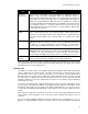
HS-3100/3200 Operator’s Manual 2.2 Miscellaneous Troubles This is a list of all possible messages that can be displayed by Miscellaneous Trouble on the LCD. Only those conditions that are in trouble will be shown. Some of the messages are always displayed if the panel is in Test Mode. Message Description PROGRAM checksum The memory chip containing the operating program has an error in it. Reloading the operating program will correct this problem.
HS-3100/3200 Operator’s Manual Message Description BBBBBBAA 1234567812 List the status of the 8 bell circuits and the 2 auxiliary power circuits. Each column represents one circuit. A dot (.) indicates a normal condition, an S indicates a short, an O indicates an open and a G indicates a ground. Auxiliary power circuits are not supervised for opens. A bell that has been installed with the polarity the wrong way may appear as a short on the bell circuit.
HS-3100/3200 Operator’s Manual Message Description network verify ? illegal The Network Verify feature has detected that the panel listed is not this panel’s database. Update the database in this panel. Remember that it is recommended that all panels be downloaded with the same database for correct operation. network verify ? version The Network Verify feature has detected that the panel listed is running a different version of operating program and database.
HARRINGTON SIGNAL INC. FIRE ALARM Harrington Signal Inc.