DOCUMENT REV CN 780-0867 C 1012 Installation Manual FireSpy® Tracker T1000, T2000, T8000, T2000E Fire Alarm Systems
HSI #780-0867 FireSpy Tracker Installation Manual Contents 1.1 1.2 1.3 Safety messages – Please read before proceeding.................................................................. 1 Warranty ........................................................................................................................................ 2 Support .......................................................................................................................................... 2 2 Overview.............
Contents HSI #780-0867 FireSpy Tracker Installation Manual B.2 Addressable SLC devices (for use with T8000-LCU, T2000-MBCLC, and T1-MB) ............... 31 B.2.1. System Sensor ...................................................................................................................... 31 B.2.2. Harrington Signal................................................................................................................... 32 B.2.3. Apollo.......................................................
HSI #780-0867 1 1.1 FireSpy Tracker Installation Manual Preliminary Information Safety messages – Please read before proceeding People’s lives depend on your safe installation of our products. It is important to read, understand and follow all instructions shipped with this product.
HSI #780-0867 FireSpy Tracker Installation Manual Contents The programming technician is ultimately responsible for conformance to the applicable codes and purchase order. This manual cannot cover all details or contingencies which could exist in a system application. Refer to the authorized distributor if additional information is required. Specifications are subject to change without notice. 1.2 1 Warranty Harrington Signal products are covered by a limited warranty.
HSI #780-0867 2 FireSpy Tracker Installation Manual Overview 2.1 General The FireSpy Tracker series panels are sophisticated microprocessor-based fire alarm control systems suited to the various needs of commercial, industrial and institutional applications. The Tracker panel can connect to a Tracker network, a peer-to-peer network of up to 250 Tracker panels. Up to 254 points on each Signal Line Circuit (SLC) and up to 60 conventional fire detector zones can be configured.
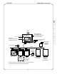
Contents HSI #780-0867 2.2 System layout 2.2.1 Standalone panel A Tracker panel consists of the main board (MB for T1000, MBC for T8000 or MBCLC for T2000) in the main enclosure and various devices that connect to the main board (see Figure 2-2). System programming can be done from a PC or laptop through the serial port of the panel’s communications adapter. 2.2.
HSI #780-0867 2.3 FireSpy Tracker Installation Manual System components The Tracker is a modular system. Each module may be purchased and installed separately. Some common system configurations are also available pre-assembled at the factory. 2.3.1 Main circuit board assembly (T1-MB, T8000-MBC, T2000-MBCLC) The main circuit board assembly (T1-MB, T8000-MBC or T2000-MBCLC) is the core of the Tracker panel. It contains the main board and power supply mounted on a metal chassis.
HSI #780-0867 FireSpy Tracker Installation Manual Table 2-1: Power supply specifications (MBC/MBCLC). Contents Parameter 1 2 Rating Input voltage (AC supply) 120VAC @ 50/60Hz 230VAC @ 50/60Hz Input current draw (AC supply) 1.8A @ 120VAC 0.4A @ 230VAC 24VDC power available (total system current) and max battery load 7A Battery charge voltage, max 27.6V Battery charge current, max 1.6A Battery capacity Min Max 8Ah 40Ah Use two UL864 listed 12V batteries connected in series.
HSI #780-0867 FireSpy Tracker Installation Manual The main circuit board contains 4 circuits (3 for MB) that can be individually programmed to operate in the following modes: • NAC (steady, temporal coding, or march time coding, Gentex 1 synchronization for Commander 3 and 4, Gentex 2 synchronization for Commander 1) • Auxiliary power supply (resettable or continuous) • Auxiliary input NOTE: UL864 requires audible alarm notification devices to be synchronized on a circuit or a system basis.
HSI #780-0867 FireSpy Tracker Installation Manual The main board contains (1) common alarm relay output, (1) common supervisory alarm relay output, and (1) common trouble relay output, as well as a connection for up to (5) relay modules (T8000-RC). Contents Table 2-9: Output relay specifications (MB / MBC / MBCLC) Parameter Rating Type Form C (SPDT) Contact rating MBC / MBCLC resistive load, PF=1.0 MB 1 * inductive load, PF=0.4 10A @ 30VDC 10A @ 240VAC* 3A @ 240VAC* resistive load, PF=1.
HSI #780-0867 2.3.4 FireSpy Tracker Installation Manual LCD annunciator (T8000-RAN / -ANN) The Tracker 8000 allows up to 15 remote display annunciators (Model T8000-ANN or T8000-RAN). The T2000 and T1000 allow up to 7 remote annunciators. The T8000-ANN remote annunciator is intended for surface or flush mounting and is comprised of the T8000-RAN module within the T8000-A-CAB cabinet. Table 2-12: Remote annunciator (T8000-RAN/T8000-ANN) specifications. Parameter Dimensions (backbox of T8000-ANN) 8.
HSI #780-0867 • Compatible with System Sensor, Apollo, Harrington and Air Productsdevices (see Appendix B for details). Mounts in the main enclosure or remotely (see Table 2-20) Contents • FireSpy Tracker Installation Manual Table 2-14: Addressable SLC module (T8000-LCU) specifications.
HSI #780-0867 2.3.8 FireSpy Tracker Installation Manual Relay module (T8000-RC) The T8000-RC relay module has (2) form C (SPDT) relays, providing individually programmable dry contact outputs. Up to (5) relay modules may be daisy-chained, with the first one connected to a conventional zone module (T8000-CM) or the main board (MB, MBC, MBCLC) via the relay output connector. Relay modules may be mounted in the main enclosure or remotely (see Table 2-20). Table 2-16: Relay module (T8000-RC) specifications.
Contents HSI #780-0867 FireSpy Tracker Installation Manual The DACT flashes the Fault LED when it recognizes a fault condition on itself. The following are the possible fault conditions. • Loss of communication with the fire panel. The DACT will attempt to communicate a trouble condition to the central station • Low or missing phone line voltage Table 2-18: T-UDACT module specifications (T2000 / T8000).
HSI #780-0867 FireSpy Tracker Installation Manual Table 2-19: City tie/reverse polarity communicator (UCT) specifications. Parameter Rating Supply voltage 24V* Input current draw 350mA max Relay contacts Trouble contacts Alarm contacts 1A @ 28VDC, form C 5A @ 28VDC, form C Remote station transmitter circuit outputs (power limited)** Voltage Current 16.5 – 24.
HSI #780-0867 FireSpy Tracker Installation Manual Contents T8000-A-CAB 1 T8000-EXP5 T8000-EXP5N Size (inches) Overall Backbox WxHxD 11.37 x 9.94 x 2.8 10 x 8.5 x 2 WxHxD 15.88 x 19.44 x 3.8 14.5 x 18 x 3 WxHxD 7.38 x 19.5 x 2.88 6 x 18.13 x 3.13 Knockouts (1-1/8 dia) 3 top 3 bottom 4 top 4 bottom 2 top 2 bottom 4 each side Module Quantity of modules that may be mounted T8000-CM 1 T8000-RC 5 T8000-RAN 5 1 2 2.
HSI #780-0867 3 FireSpy Tracker Installation Manual Installation and Wiring Installation of the panel and system accessories requires qualified, trained, and equipped personnel who are familiar with both the fire alarm codes and installation methods for this specific equipment. Final programming requires special familiarity with the applicable local codes. The versatility of this system implies sensitivity to mishandling and misprogramming beyond that of less capable equipment. 3.1 System planning 3.
HSI #780-0867 FireSpy Tracker Installation Manual Contents Annunciators should be mounted at convenient locations, at approximately eye-level. 1 2 3 3.2.3 Installation Mount the enclosure Remove circuit boards from the enclosure before mounting to avoid damage. Refer to enclosure documentation for detailed installation instructions.
HSI #780-0867 FireSpy Tracker Installation Manual Mount the door If the door was removed, remount it by installing the screw at the bottom hinge and reattaching the ground wire. For T1000, connect the cable from the annunciator on the door to the main board. Frame and mount a copy of the operating instructions found in the appendix to the wall near the panel.
HSI #780-0867 FireSpy Tracker Installation Manual All conductors not intentionally connected together must be isolated from each other and from ground. Loop resistance of each initiating and indicating circuit conductor loop must be recorded and must not exceed the resistance of the equivalent of maximum wire length and end-of-line device. Operation of lamps, LEDs, and displays Rated power supply load, and charging capability and parameters.
HSI #780-0867 FireSpy Tracker Installation Manual TYPICAL STYLE Y (CLASS B) WIRING 10K ALL NACs ARE REGULATED 24 DC USE ONLY POLARIZED DEVICES ON NACs Polarity shown is alarm condition TYPICAL STYLE Z (CLASS A) WIRING (end-of-line resistor not needed) + + LINE INPUT + P 10K 120VAC - 50/60Hz 240VAC - 50/60Hz + FH1 LINE NEU/LINE P PRIMARY PHONE RJ31X RJ31X MB P TO ANNUNCIATOR ON CABINET DOOR P RELAYS USB USB PORT + J4 SW1 - + - + COM COM NC NO COM NC S P CONTACTS RATED 2A @ 30VDC
FireSpy Tracker Installation Manual ALL NACs ARE REGULATED 24 DC USE ONLY POLARIZED DEVICES ON NACs Polarity shown is alarm condition + 120VAC - 50/60Hz 230VAC - 50/60Hz + 10K A+ B+ B- ANAC P6 J3 10K + A+ B+ B- AP8 NAC A+ B+ B- AP7 NAC A+ B+ B- AP9 NAC ALARM EARTH NEU/LINE P10 USB PORT ON/OFF 1 (U20) ETHERNET PORT (OPTIONAL) SUPV ALARM 3 LINE 2 TYPICAL STYLE Z (CLASS A) WIRING (end-of-line resistor not needed) + LINE INPUT P 1 TYPICAL STYLE Y (CLASS B) WIRING 10K 8 SW1 J4 (RESERV
HSI #780-0867 FireSpy Tracker Installation Manual TYPICAL STYLE Y (CLASS B) WIRING 10K ALL NACs ARE REGULATED 24 DC USE ONLY POLARIZED DEVICES ON NACs Polarity shown is alarm condition TYPICAL STYLE Z (CLASS A) WIRING (end-of-line resistor not needed) + LINE INPUT + 120VAC - 50/60Hz 230VAC - 50/60Hz + USB PORT A+ B+ B- AP7 NAC A+ B+ B- AP8 NAC ON/OFF 8 ETHERNET PORT (OPTIONAL) A+ B+ B- AP9 NAC (RESERVED) 8 1 SUPV ALARM EARTH NEU/LINE LINE J3 A+ B+ B- ANAC P6 1 SW3 SW1 (RESERVED) 8
FireSpy Tracker Installation Manual Contents HSI #780-0867 1 2 MB A+ B+ B- ANAC2 A+ B+ B- ANAC3 BATT A+ B+ B- ANAC1 SECNDRY PHONE PRIMARY PHONE + USB PDC RS485 RS485 - + - + SLC A- A+ B- B+ RELAY1 TROUBLE RELAYS COM AUX I/O RELAY2 3 AC power input COM NC NO COM NC NO NC CAB NO + - RC Non-power-limited areas are gray. Segregate power-limited wiring from non-power-limited wiring by at least 1/4 inch.
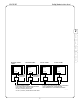
HSI #780-0867 FireSpy Tracker Installation Manual AC power input MBC Includes: chassis, MCC, keypad, and power supply modules A+ B+ B- AP5 NAC A+ B+ B- AP6 NAC SUPV ALARM TROUBLE MBC RS485 24VDC J2 P1 COM NC NO P5 COM NC NO P4 COM NC NO P3 RS485 24VDC - + - + A A+ B+ B- AP7 NAC Max 50VDC per circuit A+ B+ B- AP4 NAC ALARM J3 B CAB J1 P2 TB1 Con10M J1 D TB2 + - + - + - + - RS485 24VDC RS485 24VDC RC COM NC NO LCU LCU J2 J1 COM NC NO RC COM NC NO -A +A -B +B TB3 SLC1 J2 -A
FireSpy Tracker Installation Manual Contents HSI #780-0867 1 2 3 A+ B+ B- AP7 NAC RS485 + - J2 SHD 24VDC RS485 + - P1 + - SHD A+ B+ B- AP5 NAC A+ B+ B- AP6 NAC A+ B+ B- AP7 NAC ALARM NC NO P5 NC NO P4 COM NC SUPV ALARM COM NO P3 TROUBLE SUPV ALARM TROUBLE MBC A+ B+ B- AP4 NAC COM Max 50VDC per circuit A+ B+ B- AP6 NAC A+ B+ B- AP5 NAC ALARM A+ B+ B- AP4 NAC T2000 SYSTEM MBCLC COM NC NO P5 COM NC NO P4 COM NC Max 50VDC per circuit T8000 SYSTEM NO P3 J1 24VDC + - P2
HSI #780-0867 FireSpy Tracker Installation Manual 3 T8000 SYSTEM A T2000 SYSTEM AC power input AC power input B SUPV ALARM TROUBLE MBC RS485 24VDC P1 A+ B+ B- AP4 NAC A+ B+ B- AP5 NAC A+ B+ B- AP6 NAC A+ B+ B- AP7 NAC ALARM NC NO P5 COM NC NO P4 COM NC NO P3 RS485 24VDC - + - + J2 J3 COM MBCLC COM NC NO P5 COM NC NO P4 COM NC NO P3 Max 50VDC per circuit A+ B+ B- AP7 NAC SUPV ALARM A+ B+ B- AP6 NAC TROUBLE A+ B+ B- AP5 NAC Max 50VDC per circuit A+ B+ B- AP4 NAC ALARM J3 J1 -
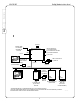
FireSpy Tracker Installation Manual Contents HSI #780-0867 MBC-LC To HAVE NAC input A+ B+ B- AP6 NAC A+ B+ B- AP7 NAC A+ B+ B- AP8 NAC A+ B+ B- AP9 NAC ALARM J3 NEU DB9M TROUBLE SERIAL EARTH 3 T2000E-CAB NC NO P5 COM NC NO P4 COM NC NO P3 J1 RS485 24VDC + - + - J2 P8 A- A+ B- B+ A- A+ B- B+ P9 P10 To UDACT / NCA Speaker zones XFMR Non-power limited areas are shaded From NAC output 1 2 3 4 5 6 7 8 11 11 1 2 3 4 5 6 7 8 Non-power limited areas must be segregated from power li
HSI #780-0867 FireSpy Tracker Installation Manual Appendix A.
HSI #780-0867 FireSpy Tracker Installation Manual Model Contents UCT 1 2 3 A Description Reference Document City tie/reverse polarity communicator A.1.3.
HSI #780-0867 FireSpy Tracker Installation Manual Appendix B. Compatible Devices B.1 Startup delay for devices with alarm verification The Tracker system includes an alarm verification feature that will result in a delay of the system alarm signal from the indicated circuits. The following statement applies to installations intended to meet UL864 requirements: The total delay (control unit plus smoke detector) shall not exceed 60 seconds.
HSI #780-0867 Harrington Part No.
HSI #780-0867 Harrington Part No.
HSI #780-0867 B.2.3. Contents Harrington Part No. 1 Apollo Apollo Model No.
HSI #780-0867 FireSpy Tracker Installation Manual Harrington Part No. Apollo Model No. Description RW-AA-N 2 wire addressable ion duct detector RW-AA-P 2 wire addressable photo duct detector MB-SDR-XP95 Sounder base MB-SDRT-AA Sounder base MB-RLY-XP95 Relay base MB-RLYT-AA Relay base MB-SDRT-SM Synchronization module for sounder and relay bases Bases Accessories B.3 Conventional two-wire smoke detectors (for use with T8000-CM) B.3.1. Harrington Signal C-Spy Series Max No.
HSI #780-0867 Max No.
HSI #780-0867 B.3.3. FireSpy Tracker Installation Manual ESL/Sentrol Max No. Detectors Per Zone Detector Model 25 25 B.3.4. Detector Identifier Base Model 429C, 521B, 521CRXT S10A N/A 429CRT, 429CSST, 429CST S11A N/A 711U, 711UT, 712U S10A 702, 702E, 701U, or 701E 713-5U, 713-6U S10A 701U, 702U, or 702E 721U, 721UD, 721UT, 722U, 731UD S10A 702U or 702E 731U, 732U S11A 702, 702E, 701RU, or 701RE Base Identifier N/A S00 System Sensor Max No.
FireSpy Tracker Installation Manual Contents HSI #780-0867 1 2 3 A B 36
HSI #780-0867 FireSpy Tracker Installation Manual Appendix C. Wire Selection C.1 General wiring guidelines Induced noise (transfer of electrical energy from one wire to another) can interfere with the communication and may cause false alarms. To avoid induced noise, follow these guidelines: • Isolate input wiring from high current output and power wiring. Do not pull one multi conductor cable for the entire panel.
HSI #780-0867 Eq. C-2 2 3 A B Worst case wire length, general form (for SLC circuits) Length_w.c. = Contents 1 FireSpy Tracker Installation Manual Vdrop ------------------------------------------------------Idraw x { Rpanel + (Rcable x DF2) + (Rdevices x DF2) } Length_w.c. is the worst case length of wire (distance from panel) in feet Vdrop is the maximum voltage drop in volts. Use 2.4 to assume 10% voltage drop on a 24V circuit.
HSI #780-0867 FireSpy Tracker Installation Manual Table 3-2: Wire Lengths for powering devices (worst case)* Load (A) * Maximum distance to farthest point (ft) 18 AWG 16 AWG 14 AWG 12 AWG 0.10 1878 2984 4753 7561 0.25 751 1194 1901 3024 0.50 376 597 951 1512 0.75 250 398 634 1008 1.00 188 298 475 756 1.25 150 239 380 605 1.50 125 199 317 504 1.75 107 171 272 432 2.00 94 149 238 378 2.25 83 133 211 336 2.50 75 119 190 302 2.
HSI #780-0867 FireSpy Tracker Installation Manual Contents Table 3-4: Wire Lengths for SLC 1 2 3 Units 18 AWG 16 AWG 14 AWG 12 AWG Belden 9571 9572 9580 9582 ohm/kFT 6.3 4.1 2.5 1.
HSI #780-0867 FireSpy Tracker Installation Manual Table 3-6: Wire Lengths for Panel Network RS485 Units 18 AWG 16 AWG 14 AWG 12 AWG Belden 9571 9572 9580 9582 ohm/kFT 6.3 4.1 2.5 1.
FireSpy Tracker Installation Manual Contents HSI #780-0867 1 2 3 A B C 42
HSI #780-0867 FireSpy Tracker Installation Manual Appendix D.
HSI #780-0867 Because Lives, Property and Businesses Aren’t Fireproof. FireSpy Tracker Installation Manual Harrington Signal Inc. 2519 4th Ave., P.O. Box 590, Moline, IL 61265 (800) 577-5758 ⋅ (309) 762-0731 ⋅ FAX (309) 762-8215 www.harringtonfire.