
User Manual


Contents
1
2
HSI #780-0867 FireSpy Tracker Installation Manual
4
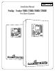
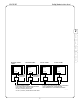
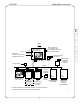
2.2 System layout
2.2.1 Standalone panel
A Tracker panel consists of the main board (MB for T1000, MBC for T8000 or MBCLC for T2000) in the
main enclosure and various devices that connect to the main board (see Figure 2-2). System
programming can be done from a PC or laptop through the serial port of the panel’s communications
adapter.
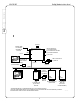
2.2.2 Multiple panel network
A Tracker network consists of multiple Tracker panels with each panel connected to the network through
a communications adapter (see 2.3.3 Network Communications adapter (T8000-NCA)). Local network
devices (annunciators, etc.) connect to the RS485 outputs of each panel, as they would in a standalone
panel. Each panel provides the same capabilities as it would as a standalone panel, with the addition of
the network connection. System programming can be done from a PC or laptop through the serial port of
the panel’s communications adapter.
NOTE: A Tracker network must include at least one T8000 panel, set up as master.
T1000
SYSTEM
(TO NETWORK)
TO PC
290-0158
* MAY BE INDIVIDUALLY CONFIGURED AS NAC, AUX POWER, OR INPUT
** MAY BE CONFIGURED AS NAC (FOR CONNECTION TO NAC BOOSTER OR VOICE MODULE) OR INPUT
A SYSTEM MUST USE AT LEAST ONE INITIATING DEVICE
MAIN BOARD ASS'Y
MB
RS485
(3) NACs*
(1) SLC
RELAY CONTACTS
(8) PER SRM
PHONE LINES
TO CENTRAL
OR REMOTE
STATION
RELAY
CONTACTS
(2) PER RC
RELAY CONTACTS
(2) PER RC
ANN
(7) MAX
IDC
(5) CLASS A OR
(10) CLASS B
PER CM
RC
(5) MAX
PER CM
CM
(6) MAX
SRM
(6) MAX
250 OUTPUTS
PER LDV
(250 TOTAL
CONFIGURABLE)
LDV
(4) MAX
RC
(5) MAX
USB
RELAY CONTACTS:
(1) SYSTEM ALARM
(1) SYSTEM SUPV ALARM
(1) SYSTEM TROUBLE
NCA
ANNUNCIATOR
(MOUNTED ON
MAIN CABINET
DOOR)
(1) AUX I/O**
1
2
3
4
5
6
7
8
9
10
SILENCE
POWER
ALARM
TROUBLE
SUPERVISORY
1
2
3
4
5
6
7
8
9
10
SILENCE
POWER
ALARM
TROUBLE
SUPERVISORY
Figure 2-2: System layout (T1000)