6800/7000 Series Frames and Power Supplies Installation and Operation Manual Edition B 175-000023-00
6800/7000 Series Frames and Power Supplies Installation and Operation Manual Edition B June 2002
Preface Purpose This manual details the features, installation procedures, operational procedures, and specifications of the 6800/7000 Series - Frames and Power Supplies. Audience This manual is written for technicians and operators responsible for installation, setup, and/or operation of 6800/7000 Series - Frames and Power Supplies.
Revision History iv Edition Date Revision History A May 1998 Original release. B June 2002 Updated Information.
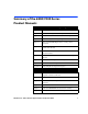
Summary of the 6800/7000 Series Product Manuals Audio/Video/Mux and Demultiplexing Manual Chapter 1 ADC-6801 CAV to SDI Converter Module Chapter 2 ADC-6880 Analog to AES/EBU Digital Convertor Chapter 3 ADM/ASM-680x Embedded Audio Monitoring Module Chapter 4 DAC-6801 Digital to Analog Component Converter Chapter 5 DAC-6880 AES/EBU Digital Audio to Analog Audio Converter Chapter 6 DEC-6801/DES-6801 Decoder/Decoder with Frame Synchronizer Module Chapter 7 DEC-6801/DES-6801M and ENC-ENS/ENX-6801A E
Routers and Distribution Manual Chapter 1 AES-6880 AES/EBU Digital Audio Distribution Amplifier Module - General Chapter 2 DNH-6800 DigiNet Hub Module Chapter 3 EDH-6800-2EDH Detection/Insertion Serial Distribution Amplifier Module Chapter 4 USM-6800 PAL/NTSC Monitoring Encoder Module Chapter 5 VCM-6801 Serial Component Monitoring Distribution Amplifier Module Chapter 6 VDA-6830 Video Distribution Amplifier Module Chapter 7 VEA-6830 Video Equalizing Amplifier Module Chapter 8 VEA-6840 Video E
Frames and Power Supply Manual Chapter 1 Mounting Frames Chapter 2 FR-6801/FR-6801-1 Frames Chapter 3 FR-6804/FR-6804-1 Frames Chapter 4 CF-6801 Cooling Frame Chapter 5 FR-7001 and FR-7000MB MIX BOX Chapter 6 6801PS Power Supply Module Chapter 7 6804(-1) Power Supply Module Chapter 8 7000 Power Supply Module Chapter 9 6801PS-48 Power Supply Module Chapter 10 6804PS-1-48 Power Supply Module 6800/7000 Series - Frames and Power Supplies Installation and Operation Manual vii
Unpacking/Shipping Information This product has been carefully inspected, tested and calibrated before shipment to ensure years of stable and troublefree service. Please check the equipment for any visible damage which may have occurred during transit. Please confirm that all items listed on the packing list have been received. If any item on the packing list is missing, please contact your Leitch dealer. If any item is damaged please contact the carrier.
Important Safety Instructions Review the following safety precautions to avoid injury and prevent damage to this product or any products connected to it. Read these instructions. Keep these instructions. Heed all warnings. Follow all instructions. Servicing Only qualified personnel should perform service procedures. Refer all servicing to qualified service personnel.
Protective ground (earth) terminal. Fuse: Replace with same type and rating of fuse. Observe precautions for handling electrostatic-sensitive devices. Injury Precautions WARNING! To reduce the risk of electric shock, do not expose this apparatus to rain or moisture. CAUTION RISK OF ELECTRIC SHOCK DO NOT OPEN WARNING! Potentially lethal voltages are present within this product’s frame during normal operation. The AC power cord must be disconnected from the frame before the top panel is removed.
AVIS - Risque de choc electrique. Ne pas ouvrir.
Use Proper Power Cord To avoid fire hazard, use only the power cord specified for this product. Ground the Product Do not defeat the safety purpose of the polarized or grounding-type plug. A polarized plug has two blades with one wider than the other. A grounding type plug has two blades and a third grounding prong. The wide blade or the third prong are provided for your safety. When the provided plug does not fit into your outlet, consult an electrician for replacement of the obsolete outlet.
Product Damage Precautions Use Proper Power Source Do not operate this product from a power source that supplies more than the specified voltage. Use Proper Voltage Setting Before applying power, ensure that the line selector is in the proper position for the power source being used. Provide Proper Ventilation To prevent product overheating, provide proper ventilation. Do Not Block Any Ventilation Openings Do not block any of the ventilation openings.
Clean Only With a Dry Cloth Keep Product Away from Heat Sources Do not install near any heat sources such as radiators, heat registers, stoves, or other apparatus (including amplifiers) that produce heat. Install Near Socket Outlet The equipment shall be installed near the socket outlet, and a disconnect device shall be easily accessible.
Battery Use Warnings CAUTION: DANGER OF EXPLOSION IF BATTERY IS INCORRECTLY PLACED. REPLACE ONLY WITH THE SAME OR EQUIVALENT TYPE RECOMMENDED BY THE MANUFACTURER. DISCARD USED BATTERIES ACCORDING TO THE MANUFACTURER’S INSTRUCTIONS. [FI Finland] VAROITUS: Paristo voi rajahtaa, jos se on virheellisesti asennettu. Vaihda paristo ainoastaan valmistajan suosittelemaan tyyppun. Havita kaytetty paristo valmistajan ohjeiden mukaisesti. [SE Sweden] VARNING: Explosionsfara vid felaktigt batteribyte.
Preventing Electrostatic Discharge CAUTION: Electrostatic discharge (ESD) can damage components in the product. To prevent ESD, observe these precautions when directed to do so: • Use a Ground Strap. Wear a grounded antistatic wrist strap to discharge the static voltage from your body while installing or removing sensitive components. • Use a Safe Work Area. Do not use any devices capable of generating or holding a static charge in the work area where you install or remove sensitive components.
Certifications and Compliances This product has been tested and found to comply with the following CE, FCC, UL, ICES and CSA standards: EMC Standards EN55014 Limits and methods of measurement of radio disturbance characteristics of electric motor-operated and thermal appliances for household and similar purposes, electric tools and similar electric apparatus. EN55022 Limits and methods of measurement of radio disturbance characteristics of information technology equipment Class A.
per the provision of the Electromagnetic Compatibility Directive 89/ 336/EEC of 3 May 1989 as amended by 92/31EEC of 28 April 1992 and 93/68/EEC, Article 5 of 22 July 1993. These devices are for professional use only and comply with Part 15 of FCC rules. Operation is subject to the following two conditions: 1. These devices may cause interference to Radio and TV receivers in residential areas 2. These devices will accept any interference received, including interference that may cause undesired operations.
For 6804-1-48 & 6801PS-48 EN 60950-1992 Safety of information technology equipment, including electrical business equipment (Amendments A1: 1993, A2: 1993, A3: 1995, A4: 1997), per the provision of the Low-Voltage Directive 73/23/EEC of February 19, 1973 as amended by 93/68/EEC. UL 1950 Safety of information technology equipment, including electrical business equipment. CSA C22.2 No. 950-95 Safety of information technology equipment, including electrical business equipment.
xx 6800/7000 Series - Frames and Power Supplies Installation and Operation Manual
Contents Chapter 1: Introducing the 6800/7000 Series of Frames ..................................................................................... 1 Overview ..................................................................................................... 1 Frame Description ......................................................................................2 Power and Frame Capacity ................................................................. 3 Installation Requirements .......................
Failure Conditions .................................................................................... 22 Buck Converter ......................................................................................... 23 Over-Current (OC) and Under-Current (UC) Sensing .................. 23 Specifications CF-6801 ............................................................................. 24 Electrical ............................................................................................ 24 Mechanical ....
Description ........................................................................................ 41 Suggested Protection Devices ........................................................... 41 Maintenance ............................................................................................. 42 Fuses .................................................................................................. 42 Power Supply Connections ...............................................................
xxiv 6800/7000 Series - Frames and Power Supplies Installation and Operation Manual
Chapter 1 Introducing the 6800/7000 Series of Frames Overview The 6800/7000 series family of frames offers a modular flexible solution to any mix of serial digital products, including a wide range of serial DAs, logo and test generators, AES processing and distribution units, ADCs, and DACs, as well as encoding and decoding modules. Input/ output functions are provided with BNC connectors, as well as a series of application-specific connection adapter modules.
Chapter 1: Introducing the 6800/7000 Series of Frames Frame Description Frame Description The 680x series of frames offers a modular flexible solution to a wide range of serial video processing and distribution functions. The following table shows a complete list and description of the 6800/7000 frames: Frame Description FR-6801/FR-6801-1 A single rack unit housing four modules, and including the 6804PS(-1) power supply unit.
Frame Description Chapter 1: Introducing the 6800/7000 Series of Frames Power and Frame Capacity The FR-6804-1 mounting frame is identical to the FR-6804 except that it has a GPI (General Purpose Interface) function as shown below: • The FR-6804-1 provides a GPI (General Purpose Interface) contact closure, indicating power supply failure. • If the 6804PS(-1) is used in the FR-6804, or the 6804PS is used in the FR-6804-1, the power supply failure indication does not function. ADC-6801 6.10 0.56 6.
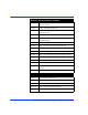
Chapter 1: Introducing the 6800/7000 Series of Frames Frame Description MXA-6800-AES 6.95 0.08 7.03 6 6 10 4 4 4 1 SAI-6800 3.87 0.00 3.87 10 9 10 9 4 4 1 USM-6800 2.79 2.53 5.31 7 6 10 6 3 3 1 VCM-6801 1.98 2.73 4.71 8 7 10 7 4 4 1 VDA-6830 0.40 0.35 0.75 10 10 10 10 4 4 1 VEA-6830 0.51 0.45 0.96 10 10 10 10 4 4 1 VES-6801 2.94 0.00 2.94 10 10 10 10 4 4 1 VFS-6801 6.37 0.17 6.54 6 5 10 5 3 3 1 VSD-6801 0.00 1.86 1.
Installation Requirements Chapter 1: Introducing the 6800/7000 Series of Frames Installation Requirements The installation requirements for the 6800/7000 series of frames are shown in the table below: Depth from Surface Frame Rack Space FR-6801/FR-6801-1 A 1RU unit that requires 1.75 in. (44 mm) of standard 19 in. (483 mm) rack space. 11 in. (280 mm) FR-6804/FR-6804-1 A 2RU unit that requires 3.5 in. (88 mm) of standard 19 in. (483 mm) rack space. 11 in.
Chapter 1: Introducing the 6800/7000 Series of Frames Installation Requirements Frame Loading Limitations Leitch 6800/7000 series frames are designed to operate in an ambient temperature range of 0° to 50°C (32° to 122°F). No special provisions are necessary other than power loading limitations that should be considered upon installation.
Maximum Frame Loading Chapter 1: Introducing the 6800/7000 Series of Frames Maximum Frame Loading If the total loading exceeds either the power supply limitations or the maximum frame loading limited, then that frame configuration is not recommended. The 6801PS (Power Supply) should not be used in the FR-6804 frames. There is a limit on the amount of total module power consumption (excluding the power supply) allowable within a given frame.
Chapter 1: Introducing the 6800/7000 Series of Frames Maximum Frame Loading Allowable Frame Configurations Follow these steps to ensure that a particular frame configuration is within allowable power limits. 1. Using the figures listed in your frame requirements, calculate the total per rail loading requirements for the positive rail and the negative rail. The sum will be the total module loading requirement. 2.
Chapter 2 FR-6801/FR-6801-1 Frames Overview The FR-6801(-1) mounting frame is a 1RU rack unit that holds up to four 6800 series modules. The FR-6801(-1) comes equipped with one power supply unit, the 6804PS(-1). This power supply provides a maximum total power of 20 W, and has a convenient flip-down front panel for easy access. Installation Requirements The FR-6801(-1) frame is a 1RU unit requiring 1.75 in. (44 mm) of standard 19 in. (483 mm) rack space. The depth from the mounting surface is 11 in.
Chapter 2: FR-6801/FR-6801-1 Frames 10 Overview 6800/7000 Series - Frames and Power Supplies Installation and Operation Manual
Chapter 3 FR-6804/FR-6804-1 Frames Overview To reduce the risk of electrical shock, plug each power supply cord into branch circuits employing separate serve grounds. The FR-6804 does not provide this feature with use of either of the power supplies. It should be noted that the FR-6802 is not top or bottom vented. The FR-6804(-1) frame is a 2RU unit. It provides a maximum of ten modules with up to eight outputs per module.
Chapter 3: FR-6804/FR-6804-1 Frames Overview The GPI is made up of two parts: • A fault sensing circuit within each power supply that monitors the primary circuit and the two output voltages. • A relay that provides isolation between Leitch equipment and the GPI output connector at the rear of the frame. There are three connections provided for GPI reporting: • Normally closed (NC) • Normally open (NO) • Ground To comply with SMPTE standards, the product uses the NC output and ground.
Overview Chapter 3: FR-6804/FR-6804-1 Frames Installation Requirements The FR-6804(-1) frame is a 2RU unit requiring 3.5 in. (88 mm) of standard 19 in. (483 mm) rack space. The depth from the mounting surface is 11 in. (280 mm). The FR-6804(-1) frame should be installed in the same rack, just below the CF-6801 cooling frame. See Chapter 4 for further information.
Chapter 3: FR-6804/FR-6804-1 Frames FR-6804(-1)/CF-6801 Installation FR-6804(-1)/CF-6801 Installation 1. Mount the FR-6804(-1) in a standard 19-inch rack with a 1RU opening above it. 2. Mount the CF-6801 directly above the FR-6804(-1). 3. Attach the DC supply cable to the DC 3-pin connector at the back of the FR-6804(-1), following the labeled positions for positive, negative, and ground. See Figure 3-1.
FR-6804(-1)/CF-6801 Installation Chapter 3: FR-6804/FR-6804-1 Frames 4. Attach the other end of the DC supply cable to the DC 5-pin connector at the back of the CF-6801 cooling frame, observing correct polarity. 5. Position the FR-6804(-1) and the CF-6801 frames at the front and the back so that the vents are aligned. 6. Plug the main power cable into the left power receptacle in the back of the FR-6804(-1). 7. Plug the other end of the main power cable into the studio power supply outlet.
Chapter 3: FR-6804/FR-6804-1 Frames Failure Conditions Failure Conditions If neither LED is illuminated, remove power to the fan tray unit immediately. Extended duration of this short circuit condition will cause damage to both the fan tray circuitry and the external power supply. To turn off the power to the fan tray, follow these instructions: 1. Pull the black locking pins on each end of the FR-6804(1) front panel until they snap out of position. These pins remain attached to the panel. 2.
Chapter 4 CF-6801 Cooling Frame Overview The CF-6801 is a one rack unit (1RU) frame fan tray with a high-airflow fan array. It provides redundant, low-noise cooling for up to two 2RU frames of equipment (4RU), or up to twenty 6800/7000 series modules. This fan array provides 40 cubic feet per minute (cfm) of airflow, evacuating from the frames below it, and exhausting into the rear of the rack. Installation Requirements The CF-6801 supplies forced air cooling for the power supply and the frame.
Chapter 4: CF-6801 Cooling Frame Overview The drawing below describes the output of the CF-6801 cooling frame. Note that 1RU of open rack space is required when the CF-6801 is used to cool two FR-6804 frames. CF-6801 85 W max. FR-6804(-1) 75 W max. FR-6804(-1) Other Manufacturer’s Equipment DC Power Connection 75 W max. DC Power Connection 75 W max. DC Power Connection 75 W max. DC Power Connection CF-6801 85 W max. 75 W max. FR-6804(-1) DC Power Connection FR-6804(-1) CF-6801 85 W max.
FR-6804(-1)/CF-6801 Installation Chapter 4: CF-6801 Cooling Frame FR-6804(-1)/CF-6801 Installation To properly install the CF-6801 with the FR-6804(-1), follow this procedure: 1. Mount the CF-6801 directly above the FR-6804(-1). 2. Attach the DC supply cable to the DC 3-pin connector at the back of the FR-6804(-1), following the labeled positions for positive, negative, and ground. 3.
Chapter 4: CF-6801 Cooling Frame FR-6804(-1)/CF-6801 Installation 4. Arrange the FR-6804(-1) and the CF-6801 frames at the front and the back so that the vents are aligned. 5. Plug the main power cable into the left power receptacle in the back of the FR-6804(-1). 6. Plug the other end of the main power cable into the studio power supply outlet. After completing the installation procedure, verify that the CF-6801 is correctly installed: 1.
LEDs Chapter 4: CF-6801 Cooling Frame LEDs A green LED indicates that power is supplied to the unit, while a red LED indicates a failure sensed by a contact closure. There are five criteria for failure in the CF-6801, indicated by the LEDs and listed in the table below. See “Failure Conditions”, on page 22. LED Condition Function Over-Current Sensing (red) If one or more of the fans short out, this LED illuminates and the GPI closes.
Chapter 4: CF-6801 Cooling Frame Failure Conditions Failure Conditions Remove power to the fan tray unit immediately if both the red and green LEDs are extinguished as this indicates a short circuit failure condition. Extended duration of this condition will cause damage to both the fan tray circuitry and the external power supply. Follow the instructions to turn off the power to the fan tray: 1. Pull the black locking pins on each end of the FR-6804(-1) front panel until they snap out of position.
Buck Converter Chapter 4: CF-6801 Cooling Frame Buck Converter The buck converter specifications are as follows: V in (max.) 15 V V out 9.5 V (3%) Efficiency 96.4% Frequency 100 KHz Imax 1.1 A The buck converter is protected against voltages in excess of 15 V by the Zener diode D13 and by resistor R43. This structure clamps the voltage across U3 in the case of an over-voltage.
Chapter 4: CF-6801 Cooling Frame Specifications Specifications Electrical Item Specification Power Supply and + 6.5 V Rails 13 VDC (from -6.5 V and +6.5 V rails) Connector 3-wire screw terminal DC Cable 22 AWG, shielded, twisted pair or equivalent Item Specification Height 1.75 in. (44 mm) Width 19 in. (483 mm) Depth 11 in. (280 mm) Weight (nominal) 4.95 lbs (2.
Chapter 5 FR-7001 and FR-7000MB MIX BOX Overview The FR-7001 frame is a single rack unit (1RU). It includes one 6801PS Power Supply and can house up to four processing modules and their appropriate interface modules (back-boxes). The FR-7000MB MIX BOX frame is designed for standalone operation. Each unit houses a single module and a 7000PS Power Supply. The FR-7000MB has a detachable power supply cord and each MIX BOX requires its own power supply cord.
Chapter 5: FR-7001 and FR-7000MB MIX BOX Installation Requirements Installation Requirements The FR-7001 frame is a 1RU unit that requires 1.75 in. (44 mm) of standard 19 in. (483 mm) rack space. The depth from the mounting surface is 11 in. (280 mm). The FR-7000MB MIX BOX is a 1RU high, 1/3 RU wide single-module frame. A MMT-03 Mounting Tray holds up to three MIX BOXES for rack mounting. LEDs The CF-6801 and the FR-7000MB are the only mounting frames in this series that have front panel LEDs.
Chapter 6 6801PS Power Supply Module Overview The model 6801PS power supply is a two-stage switching power supply that provides the following outputs: • +6.5 V @ 3.4 A =22.1 W • - 6.5 V @ 3.4 A =22.1 W Maximized efficiency and minimized individual component temperature rise has been achieved with a two stage design consisting of an input Buck converter feeding a high efficiency Push-Pull output stage.
Chapter 6: 6801PS Power Supply Module 28 Overview 6800/7000 Series - Frames and Power Supplies Installation and Operation Manual
Chapter 7 6804PS-1 Power Supply Module Overview The high efficiency 6804PS(-1) power supply is a self-contained, plug-in, auto-sensing module that accepts line voltages from 90 to 265 VAC. An external DC power connector allows several frames to be connected in parallel to back up the supply of power without redundant supplies. The FR-6804(-1) has space dedicated to an optional second 6804PS(-1) unit when redundant (standby backup) power is required.
Chapter 7: 6804PS-1 Power Supply Module Design Features Design Features The 6804PS(-1) is a two-stage, switching power supply that provides the following outputs: • +6.5 V @ 12 A • - 6.5 V @ 4.5 A To maximize efficiency and to minimize individual component temperature rise, the 6804PS(-1) has a two-stage design comprising an input Buck converter feeding a high-efficiency push-pull output stage.
GPI Fault Reporting Chapter 7: 6804PS-1 Power Supply Module GPI Fault Reporting The GPI (General Purpose Input) is made up of two parts: • A fault sensing circuit inside each power supply that monitors the primary circuit and the two output voltages. • A relay that provides isolation between Leitch equipment and the GPI output connector at the rear of the frame.
Chapter 7: 6804PS-1 Power Supply Module Specifications Specifications The following lists the electrical specifications for the GPI. Electrical Item Specification Power Input 90 - 265 VAC Connector 3-wire screw terminal Voltage Output ± 6.5 VDC Item Specification Height 3.15 in. (80 mm) Width 1.58 in. (40 mm) Depth 11.23 in. (285 mm) Weight (nominal) 1.25 lbs (0.
Emergency Shutdown Chapter 7: 6804PS-1 Power Supply Module Emergency Shutdown To shut off power in an emergency, follow these instructions: 1. Turn or push the ON/OFF switch to the OFF position. 2. Check that neither the green or the red LED is lit (this may take a few seconds). 3. Remove the power supply from the frame. Power to the frame now is now shut off.
Chapter 7: 6804PS-1 Power Supply Module 34 Emergency Shutdown 6800/7000 Series - Frames and Power Supplies Installation and Operation Manual
Chapter 8 7000PS Power Supply Module Overview The 7000PS is a universal input power supply capable of operating over the line input range of 90 to 265 VAC. The power supply produces two identical outputs of opposite polarity with a total output power of 10 W.
Chapter 8: 7000PS Power Supply Module Output Voltage Selection Output Voltage Selection Ouput voltage is controlled by selection of jumpers J1-J4 for positive voltage, and jumpers J5-J8 for negative output. Installing jumpers J2 and J4 connects the nominal 7 V ending to the output rectifier filter circuitry. This allows the power supply to be adjusted to 6 or 8 V output. Installing jumpers J1 and J3 connects the 13 volt winding to the output circuitry and gives a 13 V output.
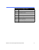
Output Voltage Selection Chapter 8: 7000PS Power Supply Module Power Supply The following table lists the power supply settings: Frame Voltage FR-1302MB ±8 FR-7000MB ±6 FR-680MB ±13 FR-880MB ±21 6800/7000 Series - Frames and Power Supplies Installation and Operation Manual 37
Chapter 8: 7000PS Power Supply Module 38 Output Voltage Selection 6800/7000 Series - Frames and Power Supplies Installation and Operation Manual
Chapter 9 6801PS-48 Power Supply Module Overview The serial distribution amplifiers VSD-6801 and VSE-6801 and the analog video distribution amplifiers VDA-6830 and VEA-6830 can now be used in -48 VDC power systems.The 6801PS-48 provides -48 VDC input and ±-6.5V outputs for the 6800 series of mounting frames.
Chapter 9: 6801PS-48 Power Supply Module Installing the 6801PS-48 Installing the 6801PS-48 Precautions To reduce the risk of electric shock or energy hazards, heed the following cautions: • Connect the 6801PS-48 to a reliably grounded SELV source or a centralized DC source. • The branch circuit overcurrent protection must be rated a maximum 10 A circuit breaker in series with a maximum 5 A listed fuse. (See suggested protection devices on page 41.) • Use 14 AWG solid copper conductors only.
Branch Circuit Schematic Chapter 9: 6801PS-48 Power Supply Module Branch Circuit Schematic Description The 6801PS-48 Power Supply differs from other Leitch power supplies in that it depends on the studio’s installed circuit breaker/fuse to disconnect power to the frame. Breaker Switches 10 A Type Eaton Heinemann series AM/S Part # AM1S-B2-A-A-02J-H-A-52-NO-10-10 5 A Fuse Panel Type Buss GMT-5 - 1 + 2 To 6801PS-48 -48 VDC Supply 3 Figure 9-3.
Chapter 9: 6801PS-48 Power Supply Module Maintenance Maintenance Fuses The replacement fuse (F1) for the 6801PS-48 is a Wickman 19194-2.5 A, 250 V fuse. For continued protection against fire, replace only with the same type and rating fuse. Power Supply Connections Use the XLR connector at the back of the power supply or frame (if the 6801PS-48 is installed in a frame) to make the following pin connections for the 6801PS-48. Pin Number Connection 1 -48 V 2 0V 3 chassis 2 1 3 Figure 9-4.
Chapter 10 6804PS-1-48 Power Supply Module Overview The 6804PS-1-48 Power Supply provides increased power output compared to the 6801PS-48 unit. The serial distribution amplifiers VSD-6801, VSE-6801 and analog distribution amplifiers VDA-6820 and VEA-6830 can now be used in -48VDC power systems requiring the FR-6804 (2RU) frame.
Chapter 10: 6804PS-1-48 Power Supply Module Installation Installation Precautions To reduce the risk of electric shock or energy hazards, heed the following cautions: • Connect the 6804PS-1-48 to a reliably grounded SELV source or a centralized DC source. • The branch circuit over-current protection must be rated a maximum 10 A circuit breaker in series with a maximum 5 A listed fuse. (See suggested protection devices page 45.) • Use 14 AWG solid copper conductors only.
Branch Circuit Schematic Chapter 10: 6804PS-1-48 Power Supply Module Branch Circuit Schematic Description The 6804PS-1-48 Power Supply differs from other Leitch power supplies in that it depends on the studio’s installed circuit breaker/fuse to disconnect power to the frame. Suggested Protection Devices Suggested breaker switch type: Eaton Heinemann, series AM/S, part # AM1S-B2-A-A-02J-H-A-52-NO-10-10 or equivalent. Suggested branch circuit fuse type: Buss part # GMT-5 or equivalent.
Chapter 10: 6804PS-1-48 Power Supply Module Maintenance Maintenance Fuses The replacement fuse (F1) for the 6804PS-1-48 is a Wickmann 19415 000 00 5A 5 x 20 mm fast acting fuse For continued protection against fire, replace only with the same type and rating fuse.
Specifications Chapter 10: 6804PS-1-48 Power Supply Module Specifications Input and Output Voltages Item Specification Input ± 48VDC ± 35 VDC to ± 65VDC Output ± 6.5 VDC output Nominal 40-62 VDC 4 A max. Power Dissipation (with Cooling Frame) Item Specification Total Power 85 W Positive Rail Support Up to 78 W max. Negative Rail Support Up to 29 W max. Power Dissipation Item Specification Total Power 75 W Positive Rail Support Up to 78 W max. Negative Rail Support Up to 24 W max.
Chapter 10: 6804PS-1-48 Power Supply Module 48 Specifications 6800/7000 Series - Frames and Power Supplies Installation and Operation Manual
A brand of Harris Corporation Harris and Leitch are registered trademarks of Harris Corporation. Trademarks and tradenames are the property of their respective companies. Broadcast Communications Division 4393 Digital Way | Mason, OH USA 45040 | Tel: 1 (513) 459 3400 www.broadcast.harris.