
Owners manual
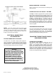
Table Of Contents

NOTE: The above diagram shows the two-way check
valve installed in a dual air system to actuate the Hayes
controller. On older vehicles with a single air brake system,
the controller should be connected from the service line
through a check valve to the controller.
ELECTRICAL CONNECTIONS
OF CONTROLLER
BATTERY CONNECTION – BLACK WIRE
The black wire is the positive voltage power supply line.
Using a 12 gauge wire, connect through a 20 amp automatic
reset circuit breaker to positive side at the battery or starter
solenoid (Figure 2). Route the wire through a grommeted
hole in the firewall to the black wire of the controller.
BRAKE CONNECTION – BLUE WIRE
Using a 12 gauge wire, connect the blue wire directly to the
trailer brake wire.
CONTROLLER STOP LIGHT CIRCUIT – RED WIRE
The Hayes controller is equipped with a separate stop light
switch, which is independent of the controller rheo-stat. Full
trailer stop light current is provided immediately upon manual
application. To provide trailer stop light operation when the
controller is manually applied, it is necessary to wire the
controller into the stop light circuit. To do this, connect the
red controller lead to the stop light switch wire that leads to
the turn signal switch as shown in Figure 2. Locate the
correct wire with a grounded test light. The correct wire is
the wire that lights the test bulb only when the tow vehicle
brakes are applied.
TWO WAY CHECK
VALVE
TRAILER BRAKE GROUND WIRE
One of the most important phases of the circuit is the proper
grounding of the trailer brakes. Never depend on establish-
ing a ground through the trailer hitch. The best possible
ground is established by running a wire from the trailer brake
ground wire connector to the battery ground wire.
BALANCING TOWING TRAILER VEHICLE
AND BRAKE SYSTEMS
CONTROLLER ADJUSTMENT
The controller handle adjustment affects the rate of
application of the trailer brakes. This adjustment has no
bearing on the maximum braking capacity of the trailer
brakes. This adjustment should be made to provide for a
slight lead of the trailer brakes over the tow vehicle brakes.
Turning the handle clockwise will decrease the rate of
application of the trailer brakes, while counter clockwise will
increase the rate of application. When the desired setting is
reached, the controller will hold the adjustment.
WARNING
THE POWER SUPPLY WIRE MUST BE A
COMPLETE
LY SEPARATE CIRCUIT FROM
THE BATTERY OR STARTER SOLENOID TO
THE CONTROLLER. DO NOT ATTACH THE
POWER SUPPLY WIRE TO ANY TOW
VEHICLE WIRING USED FOR OTHER
ACCESSORIES OR TRAILER CIRCUITS.
THIS COULD CAUSE INTERFERENCE WITH
OTHER ACCESSORIES OR OVERLOAD
CIRCUITS WHICH WOULD CAUSE BLOWN
FUSES OR CIRCUIT BREAKERS.
Hayes Brake Controller Company
1030 Sundown Drive NW •
Arab, AL 35016 USA
PH: 800-882-1204 / Tech Support 800-892-2676
Form No. 7-1064 (6/02)