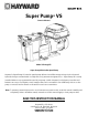
IS2603VSP Rev-A Super Pump® VS Owner’s Manual Model SP2603VSP Super Pump VS Variable Speed Pump Hayward’s Super Pump VS variable speed pump delivers incredible energy savings via its advanced hydraulic design combined with a totally enclosed, permanent magnet motor.
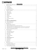
Table of Contents 1. 2. IMPORTANT SAFETY INSTRUCTIONS ................................................................................................................. 4 General Information ........................................................................................................................................ 7 2.1. Introduction 7 2.2. Primary Features 7 2.3. Product Dimensions 7 3. Energy Efficiency Overview ..................................................................................
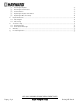
9.2. Removing the Impeller 27 9.3. Removing the Ceramic Seat 27 9.4. Seal Installation 27 9.5. Replacing the Impeller and Diffuser 27 9.6. Replacing the Motor Assembly 28 10. Replacement Parts ........................................................................................................................................28 10.1. Parts Diagram 28 10.2. Parts Listing 29 11. Troubleshooting ..................................................................................................................
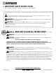
1. IMPORTANT SAFETY INSTRUCTIONS Before installing or servicing this electrical equipment, turn power supply OFF. Basic safety precautions should always be followed, including the following: Failure to follow instructions may result in injury. This is the safety-alert symbol. When you see this symbol on your pump or in this manual, look for one of the following signal words, and be alert to the potential for personal injury.
WARNING – Pool and spa components (seals, gaskets, etc.) have a finite life. All components should be inspected frequently and replaced at least every ten years, or if found to be damaged, broken, cracked, missing, or not securely attached. WARNING – Risk of Electric Shock. All electrical wiring MUST be in conformance with applicable local codes, regulations, and the National Electric Code (NEC). Hazardous voltage can shock, burn, and cause death or serious property damage.
WARNING – To Reduce the risk of Entrapment Hazards: When outlets are small enough to be blocked by a person, a minimum of two functioning suction outlets per pump must be installed. Suction outlets in the same plane (i.e. floor or wall), must be installed a minimum of three feet (3’) [0.91 meter] apart, as measured from near point to near point. Dual suction fittings shall be placed in such locations and distances to avoid “dual blockage” by a user.
2. General Information 2.1. Introduction This manual contains information for the proper installation and operation of the Hayward Super Pump VS Variable Speed Pump. The instructions in this manual MUST be followed precisely. 2.2.
3. Energy Efficiency Overview The energy consumed by a pool pump is measured in terms of Watts (W) or Kilowatts (kW). The Super Pump VS Variable Speed Pump displays power consumption in Watts. Given this information, you can determine the cost of operating the pump: Power consumption of pump X Cost of electricity = Cost of Pump Operation per Hour Example: Super Pump VS Variable Speed Pump operating at 300 W. Cost of electricity = $0.10 per kWh Convert Watts to Kilowatts: 300 W = 0.3 kW 0.3 kW X $0.
4.2. Pump Mounting Install pump on a level concrete slab or other rigid base to meet all local and national codes. Secure pump to base with screws or bolts to further reduce vibration and stress on pipe or hose joints. The base must be level, rigid, and vibration free. Pump mount must: Allow pump inlet height to be as close to water level as possible. Allow use of short, direct suction pipe (to reduce friction losses). Allow for valves in suction and discharge piping.
4.5. Electrical WARNING – All electrical wiring MUST conform to local codes, regulations, and the National Electric Code (NEC). WARNING – Ground and bond pump before connecting to electrical power supply. Failure to ground and bond pump can cause serious or fatal electrical shock hazard. Do NOT ground to a gas supply line. To avoid dangerous or fatal electrical shock, turn OFF power to pump before working on electrical connections. Fire Hazard match supply voltage to pump nameplate voltage.
4.10. Remote Control Wiring/Operation Super pump VS can be controlled in a wide variety of ways as described below: 1. Super Pump VS can operate by itself in Stand-Alone Mode using its built-in programmable timers. 2. Super Pump VS can also be controlled from third party controls (i.e. another manufacturer’s control) and Hayward controls that are not software compatible using relay contacts. See section 5.
4.12. Interface Wall Mounting The interfa ace can also be b wall mountted using the parts supplied d in the optional wall moun nt kit using the following procedure e. 1. TURN OFF THE ELEC CTRICAL POWE ER AT THE CIR RCUIT BREAKE R. 2. Loose otor drive and en the two scre ews securing the user interrface to the mo d remove the u user interface e. (Figurre 4.12-1) 3. Disconnect the sho ort cable that extends e out frrom the motorr drive to the u user interface. (Figure 4.12--1) 4.
Fig gure 4.12-2: Re emoving the Interface Mou unting Plate to o access the D Drive wiring co ompartment A the Bllank Cover Figure 4.
Figure 4.12-4: Wall Mounting the Interface 4.13. Installation Procedure Please review sections 4.1 through 4.12 before continuing with this section. 1. TURN OFF THE ELECTRICAL POWER AT THE CIRCUIT BREAKER AND REMOVE THE USER INTERFACE. 2. Loosen the two screws securing the user interface to the motor drive and remove the user interface. Disconnect the short cable that extends out from the motor drive to the user interface.
5. Wiring Diagrams 5.1. Input Power Wiring (Required) Figure 5.1-1 DRIVE HIGH VOLTAGE CONNECTIONS 5.2. Wall Mounted Digital Control Interface Wiring (Optional) Figure 5.2-1 Connection wire must be rated for a minimum of 300V, and may be up to 500 feet in length. Use removable 4-position terminal block connectors for wiring connection to interface and motor drive PCB’s taking care to note the wire colors and corresponding numbers next to the connectors.
5.3. External Relay Speed Control Wiring (Optional, for remote selection of pump speed) Note: For third party controls and Hayward controls that are NOT software compatible. Figure 5.3-1 Connection wire must be rated for a minimum of 300V. Inputs are rated to accept a low voltage supply of 18-30VAC (24VAC+/-20%) or 9-30VDC (12/24VDC +/-20%).
5.4. Hayward Automation Control Wiring (Optional, for remote control of pump speed) Note: For software compatible Hayward controls only. Existing user interface wiring connections must be removed from 4-position terminal block connector and must be covered/secured inside wiring compartments prior to making wiring connections shown below. Figure 5.4 1 The Super Pump VS pump can communicate with and be controlled by Hayward pool controls such as OmniLogic™, ProLogic®, E-Command® 4, and OnCommand®.
5.5. Remote Stop Switch Wiring (Optional) Figure 5.5-1 Connection wire must be rated for a minimum of 300V. Switch must be latching type; pump is stopped when circuit is closed. Inputs are rated to accept a low voltage supply of 18-30VAC (24VAC +/-20%) or 9-30VDC (12/24VDC +/-20%). The “+12V” and “COM” terminals may be used as a low voltage supply. These terminals also supply to the user interface , so care must be taken when connecting to these terminals to ensure proper operation of user interface.
6.2. Starting/Priming the Pump Refer to item #9 in section 6.6 for priming time selection. Fill strainer housing with water to suction pipe level. If water leakage occurs from anywhere on the pump or filter, DO NOT start the pump. If no leakage occurs, stand at least 10 feet from pump and/or filter and proceed with starting the pump. WARNING – Return to filter to close filter manual air relief valve when a steady stream of water (not air or air and water) is discharged from valve.
6.3. User Interface Summary Figure 6.3-1 1. Preset Speeds: Buttons labeled SPEED 1 thru SPEED 4 can be used to run the pump at a predetermined speed for a certain length of time. Preset Speed settings can be quickly updated using the + and - arrow buttons to change the speed and then pressing the > button to save the new speed setting. When a speed is selected, the LED beside the button will illuminate to indicate operation. a.
6.4. Menu Outline 1. Configuration Menu (see section 6.6 for basic product configuration) a. Set Day and Time b. Speed Selection c. MAX Allowed Speed d. MIN Allowed Speed e. Prime Duration f. Remote Control Mode g. Low Temp Operation h. Low Temp Setting 2. Timer Menu (see section 6.7 to program the 8 speeds with timer functions) a. Rename Timer “X” (where “X” equals 1 through 8) b. Pump Speed for Timer “X” (where “X” equals 1 through 8) c. Start/Stop Time for Timer “X” (where “X” equals 1 through 8) d.
6.6. Configuration Menu Screen 1. Configuration Menu Locked 2. Configuration Menu press > to enter 3. Use + / - to adjust, > go to next item 4. Time: Th 1:27PM + change or > skip 5. Set Day and Time Thursday 1:27p 6. Speed Selection rpm 7. MAX allowed speed 3450 (600-3450rpm) 8. MIN allowed speed 600 (600-3450rpm) 9.
pump, system plumbing, or pool from freezing. If Low Temp Operation is disabled, the temperature setting screen is not shown. Buttons Used Screen Comments 13. Reset all parameters + for yes; > to skip +<> Use + to reset to factory default settings Use > to skip reset 14. Are you sure? + for yes; - for no +<> Confirm reset of all parameters Move to next menu item 15. Use Timers Menu to set timeclocks. 6.7. Timer Menu Buttons Used Screen 1. Timer Menu Press > to enter 2.
6.8. Preset Speed Setup Menu Screen 1. Speeds Menu Press > to enter 2. Speed 1 Name Speed 1 3. Speed 1 Duration 0:30 hours Buttons Used Comments <> Use > to enter Speeds Menu +<> Use to rename displayed speed Move to next menu item +<> Use to set duration of speed Move to next menu item Note: Each time a preset speed is selected, it will run for the programmed duration. Multiple presses of the speed button will add more time according to the set duration up to a maximum of 12 hours. 4.
Screen Buttons Used Comments 7. Power Usage 225W (1700W Max) Real-time display of pump power usage. 8. Drive Temperature 67ºC (110ºC Max) Real-time display of motor driver temperature. Event log Press + to view 9. +- Use + to view event log Note: For troubleshooting purposes, the Event Log will record the last twenty error/trip conditions and/or status messages, as well as the amount of time that has elapsed since the condition occurred. See section 11.2 for more detail. 6.10.
6.12. Remote Stop Screen 1. Remote Stop is engaged Note: The above message will be displayed when an installed remote stop switch is activated. For either model, the pump will remain stopped until the remote stop switch is deactivated. See section 5.5 for more detail. 7. Maintenance Clean strainer basket regularly. Do NOT strike basket to clean. Inspect strainer cover gasket regularly and replace as necessary. Hayward pumps have self-lubricating motor bearings and shaft seals.
9. Shaft Seal Change Instructions IMPORTANT SAFETY INSTRUCTIONS PLEASE READ AND FOLLOW ALL INSTRUCTIONS When servicing electrical equipment, basic safety precautions should always be observed including the following. Failure to follow instructions may result in injury. WARNING – To reduce risk of injury, do not permit children to use this product. Disconnect all electrical power service to pump before beginning shaft seal replacement. Only qualified personnel should attempt rotary seal replacement.
9.6. Replacing the Motor Assembly 13. Slide the motor assembly, with the diffuser in place, into pump/strainer housing, being careful not to disturb the diffuser gasket. 14. Fasten assembly to pump/strainer housing using the four (4) 3/8" x 2" bolts. (Be sure housing gasket is in place, and lubricated. Replace if damaged). Tighten bolts alternately and evenly to 80 inch-pounds.
10.2. Parts Listing Ref. No. Part No. Description Qty.
11. Troubleshooting 11.1. General Problems Motor Will NOT Start: 1. Make sure the terminal board connections agree with the wiring diagram on the pump data plate label. 2. Be sure the pump is wired for the available field supply voltage (230VAC). 3. Check for and correct any improper or loose wiring connections; open switches or relays; tripped circuit breakers, or blown fuses. 4. Manually check the rotation of the motor shaft for free movement and lack of obstruction. Correct if necessary.
Noisy Pump: 1. Air leak in suction piping, cavitations caused by restricted or undersized suction line or leak at any joint, low water level in pool, and unrestricted discharge return lines. Correct the suction condition or throttle return lines, if practical. Holding your hand over the return fitting will sometimes prove this, or by putting in a smaller eyeball fitting. 2. Vibration due to improper mounting, etc. Mount the pump on a level surface and secure the pump to the equipment pad. 3.
11.2. Check System Messages Code Troubleshooting Check System DC voltage too high Indicates that the DC bus voltage has risen above 400 VDC. Verify that line voltage is within 10% (207-253 VAC) of pump rated voltage at the terminal block. Check System DC voltage too low Indicates that the DC bus voltage has dropped below 230 VDC. Verify that line voltage is within 10% (207-253 VAC) of pump rated voltage at the terminal block.
12. Warranty 13.
THIS PAGE INTENTIONALLY LEFT BLANK Page 34 of 36 USE ONLY HAYWARD GENUINE REPLACEMENT PARTS Super Pump VS Pump IS2603VSP Rev-A
THIS PAGE INTENTIONALLY LEFT BLANK Page 35 of 36 USE ONLY HAYWARD GENUINE REPLACEMENT PARTS Super Pump VS Pump IS2603VSP Rev-A
FCC Compliance Statement: This device complies with part 15 of the FCC rules. Operation is subjected to the following two conditions: (1) This device may not cause harmful interference, and (2) this device must accept any interference received, including interference that may cause undesired operation. This equipment has been tested and found to comply with limits for a Class B digital device, pursuant to Part 15 of the FCC rules.