
Specification
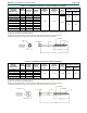

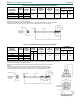
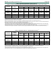

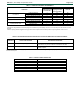
Table Of Contents

ESR-1078
|
Most Widely Accepted and Trusted Page 2 of 8
3.1.5 ThruLOK Fasteners: The ThruLOK fasteners have
a
5
/
16
-inch (7.9 mm) hex-head, rolled threads and a
proprietary cutting point. The fasteners are coated with
mechanically applied zinc in accordance with ASTM B695,
Type I, Class 55. They are supplied with the ThruLOK
washer and nut. See Table 1F for fastener dimensions and
a diagram.
3.2 Materials:
3.2.1 Fasteners: The fasteners are made of carbon steel
grade 1022 or 10B21 wire, conforming to the report
holder’s material specifications, and have a proprietary
finish. Minimum bending yield strengths of the fasteners
are listed in Tables 1A through 1F of this report.
3.2.2 Wood Members: Wood members must be solid-
sawn lumber having a minimum assigned specific gravity
as indicated in Tables 2, 3 and 4. Assigned specific gravity
for solid-sawn lumber must be determined in accordance
with Table 12.3.3A of the 2015 NDS (Table 11.3.3A of
NDS-12 for the 2012 IBC, Table 11.3.2A of NDS-05 for the
2009 and 2006 IBC).
4.0 DESIGN AND INSTALLATION
4.1 Design:
Reference withdrawal design values are given in Table 2 of
this report. Reference head pull-through design values are
given in Table 3 of this report. Reference lateral design
values for wood-to-wood connections loaded parallel and
perpendicular to the grain, are given in Table 4.
The reference design values given in Tables 2 through 4
must be multiplied by all adjustment factors applicable to
wood screws, in accordance with the NDS, including the
wet service factor, C
M
, where applicable. Reference head
pull-through design values must be adjusted using the
NDS adjustment factors applicable to withdrawal for wood
screws.
The allowable load for a single-screw connection in
which the screw is subject to tension must be taken as the
least of: (a) the reference withdrawal design value given
in Table 2, adjusted by all applicable adjustment factors;
(b) the reference head pull-through design value given in
Table 3, adjusted by all applicable adjustment factors;
and (c) the allowable screw tension strength given in
Tables 1A through 1F.
The allowable lateral load for a single-screw connection
must be taken as the lesser of: (a) the reference lateral
design value given in Table 4, adjusted by all applicable
adjustment factors, and (b) the allowable screw shear
strength given in Tables 1A through 1F.
When designing a connection, the structural members
must be checked for load-carrying capacity in accordance
with Section 11.2.3 of NDS-15 (Section 10.1.2 of NDS-12
and NDS-05 for the 2012, 2009 and 2006 IBC), and local
stresses within multiple-fastener connections must be
checked against Appendix E of the NDS to ensure the
capacity of the connection and fastener group.
Connections containing multiple screws must also be
designed in accordance with Sections 11.2.2 and 12.6 of
NDS-15 (Sections 10.2.2 and 11.6 of NDS-12 and NDS-05
for the 2012, 2009 and 2006 IBC).
Where the screws are subjected to combined lateral and
withdrawal loads, connections shall be designed in
accordance with Section 12.4.1 of the NDS-15 (Section
11.4.1 of NDS-12 and NDS-05 for the 2012, 2009 and
2006 IBC).
The FastenMaster LOK Series fasteners described in
Sections 3.1.1 through 3.1.4 are recognized for use in
wood chemically treated with waterborne alkaline copper
quaternary,
type D (ACQ-D), with a maximum retention of 0.40 pcf
(6.4 kg/m
3
). These fasteners must be limited to use in
typical applications and limitations defined in Table 6.
4.2 Installation:
The fasteners must be installed with a
1
/
2
-inch (12.7 mm),
low RPM/high torque electric drill (450 rpm) using the
driver bit included in each box. Lead holes are not
required. Fasteners must be installed at the minimum end
and edge distances listed in Table 5 of this report.
The ThruLOK fastener must be installed with the
ThruLOK washer and nut (supplied with the fastener). The
ThruLOK fastener must penetrate through the opposite
face of the main member a sufficient distance to allow the
nut to be tightened snugly against the main member, with
at least
1
/
2
inch (12.7 mm) of the threaded portion of the
shank engaging the internal threads of the nut.
5.0 CONDITIONS OF USE
The fasteners described in this report comply with, or are
suitable alternatives to what is specified in, those codes
listed in Section 1.0 of this report, subject to the following
conditions:
5.1 Design and installation of connections with
FastenMaster LOK Series fasteners must comply with
this report, the manufacturer’s published instructions
and the applicable code. In the event of a conflict
between the manufacturer’s published installation
instructions and this report, the more restrictive
governs.
5.2 Use of the fasteners in locations exposed to saltwater
or saltwater spray is outside the scope of this
evaluation report.
6.0 EVIDENCE SUBMITTED
6.1 Data in accordance with the ICC-ES Acceptance
Criteria for Alternate Dowel-type Threaded Fasteners
(AC233), dated April 2015.
6.2 Data in accordance with the ICC-ES Acceptance
Criteria for Corrosion-resistant Fasteners and
Evaluation of Corrosion Effects of Wood Treatment
Chemicals (AC257), dated October 2009 (editorially
revised May 2015).
7.0 IDENTIFICATION
Packages of fasteners are identified by the company name
(OMG or MiTek), one of the product names shown in
Table 7, the fastener size and the evaluation report
number (ESR-1078). Head markings on the fasteners
indicate fastener length and are applied as noted in Tables
1A through 1F.