Owner’s Manual Installation and Operation Model(s): CD4236MR CD4842MR CD4236MLR CD4842MLR CD4236MIR CD4842MIR CD4236MILR CD4842MILR Direct Vent Gas Appliance CAUTION WARNING If the information in these instructions is not followed exactly, a fire may result causing property damage, personal injury, or death. • Do not store or use gasoline or other flammable vapors and liquids in the vicinity of this or any other appliance. • What to do if you smell gas: - Do not try to light any appliance.
Read this manual before installing or operating this appliance. Please retain this owner’s manual for future reference. A. Congratulations Congratulations on selecting a Heatilator gas fireplace, an elegant and clean alternative to wood burning fireplaces. The Heatilator gas fireplace you have selected is designed to provide the utmost in safety, reliability, and efficiency. As the owner of a new fireplace, you’ll want to read and carefully follow all of the instructions contained in this owner’s manual.
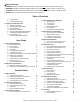
Safety Alert Key: • • • • DANGER! Indicates a hazardous situation which, if not avoided will result in death or serious injury. WARNING! Indicates a hazardous situation which, if not avoided could result in death or serious injury. CAUTION! Indicates a hazardous situation which, if not avoided, could result in minor or moderate injury. NOTICE: Used to address practices not related to personal injury. Table of Contents A. Congratulations B. Limited Lifetime Warranty 2 5 1 Listing and Code Approvals A. B.
14 Appliance Setup A. B. C. D. E. F. G. H. I. J. K. L. M. N. Remove Clean Face Components Remove Glass Assembly Remove the Shipping Materials Clean the Appliance Accessories Install the Refractory Place the Lava Rock Place the Vermiculite Place the Rockwool Install the Log Assembly Fixed Glass Assembly Install Trim Install Clean Face Components Air Shutter Setting 54 54 54 54 54 54 54 54 54 55 55 56 56 57 15 Troubleshooting A. Standing Pilot Ignition System B.
B. Limited Lifetime Warranty Gas Appliance (Fireplace) Limited Lifetime Warranty HEARTH & HOME TECHNOLOGIES INC. (“HHT”) extends the following warranty for HEATILATOR® gas appliances installed in the United States of America or Canada (the "Appliance"). Dealers and employees of HHT have no authority to make any warranty or authorize any remedies in addition to or inconsistent with the terms of this warranty.
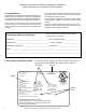
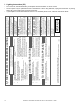
1 Listing and Code Approvals A. Appliance Certification C. BTU Specifications Caliber CD Mesh Series MODELS: CD4236MR, CD4236MLR, CD4236MIR, CD4236MILR Max/Min Input Rate (NG) LABORATORY: Underwriters Laboratories, Inc. (UL) Orifice Size (NG) TYPE: Vented Gas Fireplace Heaters NOT INTENDED FOR USE AS A PRIMARY HEAT SOURCE. This appliance is tested and approved as either supplemental room heat or as a decorative appliance.
Note: The following requirements reference various Massachusetts and national codes not contained in this document. G.
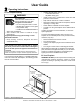
2 User Guide Operating Instructions A. Gas Fireplace Safety • WARNING HOT SURFACES! Glass and other surfaces are hot during operation and cool down. Hot glass will cause burns. • Do not touch glass until it is cooled • NEVER allow children to touch glass • Keep children away • CAREFULLY SUPERVISE children in same room as appliance. • Alert children and adults to hazards of high temperatures. High temperatures may ignite clothing or other flammable materials.
C. Fan Kit (optional) F. Fixed Glass Assembly If desired, a fan kit may be added. Contact your dealer to order the correct fan kit. See Section 14.K. G. Remote Controls, Wall Controls and Wall Switches D. Clear Space WARNING! DO NOT place combustible objects in front of the fireplace or block louvers. High temperatures may start a fire. See Figure 2.2.
Heatilator • Caliber Mesh CD Series-SIT Valve • 4040-849 Rev J • 06/08 D. C. Use only your hand to push in and move the gas control valve or turn the gas control knob. Never use tools. If the lever or knob will not move by hand, don't try to repair it, call a qualified service technician. Force or attempted repair may result in a fire or explosion. Do not use this appliance if any part has been under water.
7 8 OF F 11 Heatilator • Caliber Mesh CD Series-SIT Valve • 4040-849 Rev J • 06/08 Due to high surface termperatures, keep children, clothing and furniture away. Keep burner and control compartment clean. See installation and operating instructions accompanying the appliance. 29097D Turn manual gas valve to "CLOSED position. Do not force. Replace control access panel. 5 OFF 3. 4. 5 ON Turn off wall switch or set thermostat to lowest setting. Remove control access panel.
K. After Fireplace is Lit Initial Break-in Procedure • The fireplace should be run three to four hours continuously on high. • Turn the fireplace off and allow it to completely cool. • Remove fixed glass assembly. See Section 14.K. • Clean fixed glass assembly. See Section 3.A. • Replace the fixed glass assembly and run continuously on high an additional 12 hours. This cures the materials used to manufacture the fireplace. NOTICE! Open windows for air circulation during fireplace break-in.
3 Maintenance and Service Any safety screen or guard removed for servicing must be replaced prior to operating the fireplace. When properly maintained, your fireplace will give you many years of trouble-free service. We recommend annual service by a qualified service technician. A. Maintenance Tasks-Homeowner Installation and repair should be done by a qualified service technician only. The fireplace should be inspected before use and at least annually by a professional service person.
B. Maintenance Tasks-Qualified Service Technician Burner Ignition and Operation The following tasks must be performed by a qualified service technician. By: Qualified Service Technician Gasket Seal and Glass Assembly Inspection Frequency: Annually By: Qualified Service Technician Tools needed: Protective gloves, drop cloth and a stable work surface. • Inspect gasket seal and its condition. • Inspect fixed glass assembly for scratches and nicks that can lead to breakage when exposed to heat.
4 Installer Guide Getting Started A. Typical Appliance System NOTICE: Illustrations and photos reflect typical installations and are for design purposes only. Illustrations/diagrams are not drawn to scale. Actual product may vary from pictures in manual Note: Dual venting configurations ARE NOT allowed. Appliance MUST be vented EITHER vertically OR horizontally.
B. Design and Installation Considerations D. Inspect Appliance and Components Heatilator direct vent gas appliances are designed to operate with all combustion air siphoned from outside of the building and all exhaust gases expelled to the outside. No additional outside air source is required. • Installation MUST comply with local, regional, state and national codes and regulations.
5 Framing and Clearances A. Select Appliance Location NOTICE: Illustrations reflect typical installations and are FOR DESIGN PURPOSES ONLY. Illustrations/diagrams are not drawn to scale. Actual installation may vary due to individual design preference. When selecting a location for the appliance it is important to consider the required clearances to walls (see Figure 5.1). WARNING! Risk of Fire or Burns! Provide adequate clearance around air openings and for service access.
B. Construct the Appliance Chase To further prevent drafts, the wall shield and ceiling firestops should be caulked with high temperature caulk to seal gaps. Gas line holes and other openings should be caulked with high temp caulk or stuffed with unfaced insulation. If the appliance is being installed on a cement slab, a layer of plywood may be placed underneath to prevent conducting cold up into the room. A chase is a vertical box-like structure built to enclose the gas appliance and/or its vent system.
D. Mantel and Wall Projections WARNING! Risk of Fire! Comply with all minimum clearances to combustibles as specified. Framing or finishing material closer than the minimums listed must be constructed entirely of noncombustible materials (i.e., steel studs, concrete board, etc). Mantels Note: All measurements in inches. 30 in.
6 Termination Locations A. Vent Termination Minimum Clearances Direct Vent Gas, Wood or Fuel Oil Termination 20 in. WARNING B Gas Termination Horizontal overhang Termination Cap Storm Collar Roof Flashing (minimum) to Perpendicular Wall (DV only) 18 in. (457 mm) Fire Risk. Maintain vent clearance to combustibles as specified. • DO NOT pack air space with insulation or other materials. Failure to keep insulation or other materials away from vent pipe may cause overheating and fire. 24 in. min.
H D O E N V L V C B Fixed Closed V F B Openable Fixed Closed V V V G V B B B V J X M V I A V TERMINATION CAP K X GAS METER X AIR SUPPLY INLET Measure vertical clearances from this surface Q RESTRICTION ZONE (TERMINATION NOT ALLOWED) V P W V R U V T U V V Covered Alcove Applications Dimension Descriptions Electrical Service D* S Measure horizontal clearances from this surface.
7 Vent Information and Diagrams A. Approved Pipe Vertical 12 in . DO NOT mix pipe, fittings or joining methods from different manufacturers. The pipe is tested to be run inside an enclosed wall. There is no requirement for inspection openings at each joint within the wall. 8-1/2 in. This appliance is approved for use with Hearth & Home Technologies DVP and/or SLP venting systems. Refer to Section 16.B. for vent component information. 8-1/2 in. WARNING! Risk of Fire or Asphyxiation.
E. Vent Diagrams To replace the first starter elbow with two 45° elbows, refer to Figure 7.4. All other 90° elbows can be replaced with two 45° elbows. General Rules: • • • • • • • SUBTRACT 3 ft. from the total H measurement for each 90° elbow installed horizontally. SUBTRACT 1-1/2 ft. from the total H measurement for each 45° elbow installed horizontally. A maximum of three 90° elbows (or six 45° elbows) may be used in any vent configuration. Some elbows may be installed horizontally. See Figure 7.9.
1. Top Vent - Horizontal Termination - (continued) Two 45° Elbows replacing One 90° Elbow 4 ft min. (1.22 m) 25 ft max. (7.62 m) Figure 7.4 V1 min. Two Elbows V1 max. ft m H1+H2 max. H1+H2+H3 max. ft m ft 0.5 0.15 - - 6 1.83 - - 1 0.30 - - 11 3.35 11 3.35 1.5 0.46 - - 18 5.49 18 5.49 2 0.61 - - 25 7.62 25 7.62 DVP 25 7.62 25 7.62 25 7.62 SLP 23 7.01 25 7.62 25 7.62 Installed Vertically H3 Installed Horizontally H1 H2 H2 Figure 7.
1. Top Vent - Horizontal Termination - (continued) V1 min. Three Elbows V1 + V2 max. H1+H2 max. ft m ft m ft m DVP 1 0.30 24 7.32 19 5.79 SLP 1 0.30 22 6.71 19 5.79 Installed Vertically H2 V2 V1 H1 Figure 7.
2. Top Vent - Vertical Termination Note: If installing a vertical vent/ termination off the top of the appliance, the vertical termination baffle should be used. No Elbow 12 ft (3.66 m) min. 60 ft (18.29 m) max. Figure 7.7 Note: If installing a vertical vent/ termination off the top of the appliance, the vertical termination baffle should be used. Two Elbows 12 ft (3.66 m) min. 60 ft (18.29 m) max. Maximum horizontal run is 100% of vertical, but cannot exceed 26 ft (7.92 m) Figure 7.
2. Top Vent - Vertical Termination - (continued) Note: If installing a vertical vent/ termination off the top of the appliance, the vertical termination baffle should be used. Three Elbows Maximum horizontal run is 100% of vertical, but cannot exceed 26 ft (7.92 m) 12 ft (3.66 m) min. 60 ft (18.29 m) max. Figure 7.
3. Rear Vent - Horizontal Termination No Elbow 18 in. (457 mm) max. Figure 7.10 One 45° Elbow 18 in. (457 mm) max. Figure 7.
3. Rear Vent - Horizontal Termination - (continued) H1 max. Two Elbows V1 min. H1+H2 max. ft m ft m ft m 2 0.61 1 0.30 3 0.91 4 1.22 2 0.61 6 1.83 6 1.83 3 0.91 9 2.74 8 2.44 4 1.22 12 3.66 8 2.44 5 1.52 15 4.57 8 2.44 6 1.83 18 5.49 V1 H2 H1 Figure 7.12 Three Elbows H1 max. Installed Horizontally H3 H2 V1 min. H1+H2+H3 max. ft m ft m ft m 2 0.61 1 0.30 3 0.91 4 1.22 2 0.61 6 1.83 6 1.83 3 0.91 9 2.74 8 2.44 4 1.22 12 3.
4. Rear Vent - Vertical Termination One Elbow 0 min. 6 ft (1.83 m) max. 12 ft (3.66 m) min. 60 ft (18.29 m) max. Figure 7.14 Two Elbows 12 ft (3.66 m) min. 60 ft (18.29 m) max. 0 min. 6 ft (1.83 m) max. Maximum horizontal run is 100% of vertical, but cannot exceed 26 ft (7.92 m) Figure 7.
4. Rear Vent - Vertical Termination - (continued) Three Elbows 0 min. 6 ft (1.83 m) max. 12 ft (3.66 m) min. 60 ft (18.29 m) max. Maximum horizontal run is 100% of vertical, but cannot exceed 26 ft (7.92 m). Figure 7.
F. Install Vertical Termination Baffle Note: For vertically terminated installations only. • Note: If installing a vertical vent/termination run off the top or rear of the appliance, the vertical termination baffle supplied with the appliance may be used. • Remove the glass (refer to Section 14.K.) to access the firebox and 5 in. inner flue. • Fold the baffle (Figure 7.17) to an approximate 90° angle (see Figure 7.18). Squeeze the open end of the bent baffle with one hand.
8 Vent Clearances and Framing A. Pipe Clearances to Combustibles B. Wall Penetration Framing WARNING! Risk of Fire! Maintain air space clearance to vent. DO NOT pack insulation or other combustibles: Combustible Wall Penetration • • • Between ceiling firestops Between wall shield firestops Around vent system Failure to keep insulation or other material away from vent pipe may cause over heating and fire. Note: Heat shields MUST overlap by a minimum of 1-1/2 in. (38 mm).
C. Install the Ceiling Firestop A ceiling firestop MUST be used between floors and attics. • DVP pipe only - Frame an opening 10 in. by 10 in. (254 mm by 254 mm) whenever the vent penetrates a ceiling/fl oor (see Figure 8.3). • SLP pipe only - Frame opening 9 in. x 9 in. (229 mm x 229 mm) whenever the vent penetrates a ceiling/floor (see Figure 8.3). • Frame the area with the same sized lumber as used in ceiling/floor joist.
D. Install Attic Insulation Shield WARNING! Fire Risk. DO NOT allow loose materials or insulation to touch vent. Hearth & Home Technologies Inc. requires the use of an attic shield. The National Fuel Gas Code ANSI Z223.1 and NFPA 54 requires an attic shield constructed of 26 gauge minimum metal that extends at least 2 in. (51 mm) above insulation. Attic shields must meet specified clearance and be secured in place. Flat Ceiling Installation • Remove one shield from box.
9 Appliance Preparation A. Convert from Top Vent to Rear Vent • CAUTION! Risk of Cuts, Abrasions or Flying Debris. Wear protective gloves and safety glasses during installation. Sheet metal edges are sharp. Remove three remaining screws holding the plate surrounding flue. See Figure 9.3. Remove plate and set aside. NOTICE: Once appliance is set up for top or rear venting, it CANNOT be changed at a later time. • Remove the screw holding heat shield cover plate to top of appliance and set aside.
• Remove four screws holding outer collar to appliance top. See Figure 9.5. Remove outer collar. • Remove four screws holding outer cover plate to appliance back. See Figure 9.8. Remove outer cover. Figure 9.8 • Figure 9.5 • Outer Collar, Remove Four Screws Remove four screws holding inner cover plate to appliance back. See Figure 9.9. Remove inner cover. Remove four screws holding inner collar to appliance top. See Figure 9.6. Remove inner collar. Figure 9.9 Figure 9.
• Place outer collar on rear of appliance and replace four screws to hold collar in place. See Figure 9.11. Make sure insulation is attached to the collar base! • Place inner cover plate on appliance top and replace four screws to hold inner cover plate in place. See Figure 9.14. Make sure gasket is replaced with the cover plate! Figure 9.11 Place Outer Collar on Rear of Appliance • Locate the cover plate removed in the second step.
• Locate heat shield cover plate removed in the first step. Place the heat shield cover plate on top of heat shield. Replace four screws to hold this plate in place. See Figure 9.16. Figure 9.18 Screw Cover into Place • Figure 9.16 Cover Plate-Replace • The appliance should look like the one shown in Figure 9.19 after it has been converted to a rear vent appliance. Locate outer shell cover removed in the sixth step (Figure 9.7). Place the cover on top of appliance. See Figure 9.17.
B. Secure and Level the Appliance WARNING! Risk of Fire! Prevent contact with: • • • Sagging or loose insulation Insulation backing or plastic Framing and other combustible materials Block openings into the chase to prevent entry of blown-in insulation. Make sure insulation and other materials are secured. DO NOT notch the framing around the appliance standoffs. Failure to maintain air space clearance may cause overheating and fire.
10 Install Vent Pipe A. Assemble Pipe Sections (DVP Only) Attach Pipe to the Firebox Assembly Note: The end of the pipe sections with the lanced tabs will face towards the appliance. Attach the first pipe section to the starting collar: • • • • Lanced pipe end to the starting collar Inner pipe over inner collar Push the pipe section until all lanced tabs snap in place Lightly tug on pipe to confirm it has locked.
B. Assemble Vent Sections (SLP Only) To attach the first vent component to the starting collars of the appliance • Attach an SLP-DVP24 adapter to the starting collar of the appliance. Lock the vent components into place by sliding the pipe section onto the collar. Align the seam of the pipe and seam of collar to allow engagement. Rotate the vent component to lock into place. Use this procedure for all vent components. See Figure 10.5.
D. Secure the Vent Sections E. Disassemble Vent Sections • • • • • • • Vertical runs of DVP pipe must be supported every 8 ft. (2.44 m) after the 25 ft. (7.62 m) maximum unsupported rise. Vertical runs of SLP pipe must be supported every 8 ft. (2.44 m). Horizontal sections of vent must be supported every 5 ft. (1.52 m) with a vent support or plumber’s strap. Wall shield firestops may be used to provide horizontal support. Vent support or plumber’s strap (spaced 120° apart) may be used for support.
F. Install Decorative Ceiling Components (SLP only) Level A decorative ceiling thimble can be installed on a flat ceiling through which the vent passes. The decorative ceiling thimble is used to cover the firestop, which is installed according to section 8.C. Cathedral ceiling support box • Seal the gap between the vent pipe and firestop using high temperature silicone to prevent cold air infiltration.
G. Install Metal Roof Flashing H. Assemble and Install Storm Collar Note: Skip to Section 10.I. if using the RF4-8. • See minimum vent heights for various pitched roofs (Figure 10.14) to determine the length of pipe to extend through the roof. • Slide the roof flashing over the pipe sections extending through the roof as shown in Figure 10.16. Horizontal overhang 24 in. min. (610 mm) Termination Cap 20 in.
I. Install RF4-8 The RF4-8 may be used in place of the roof flashing and storm collar (Sections 10.G. and 10.H.) Pipe must be supported within 12 in. (305 mm) of the roofline using plumbers strapping or an SLP-FS when using the RF4-8 Flashing. Refer to Sect. 8.C. Securing Vent Sections. Secure with 4 screws no longer than 1/2 in./13 mm Figure 10.20 Apply Sealant SLP-FS Figure 10.
J. Install Vertical Termination Cap • • Attach the vertical termination cap by sliding the inner collar of the cap into the inner flue of the pipe section while placing the outer collar of the cap over the outer flue of the pipe section. Secure the cap by driving three self-tapping screws (supplied) through the pilot holes in the outer collar of the cap into the outer flue of the pipe (see Figure 10.23). Termination Cap L.
M. Install Horizontal Termination Cap • WARNING! Risk of Fire! The telescoping flue section of the termination cap MUST be used when connecting vent. • 1-1/2 (38 mm) minimum overlap of flue telescoping section is required. Failure to maintain overlap may cause overheating and fire. • • Vent termination must not be recessed in the wall. Siding may be brought to the edge of the cap base. Flash and seal as appropriate for siding material at outside edges of cap.
11 Gas Information A. Fuel Conversion C. Gas Connection • • • Make sure the appliance is compatible with available gas types. Conversions must be made by a qualified service technician using Hearth & Home Technologies specified and approved parts. • • B. Gas Pressure • • • Optimum appliance performance requires proper input pressures. Gas line sizing requirements will be determined in ANSI Z221.3 National Fuel Gas Code in the USA and CAN/ CGA B149 in Canada.
12 Electrical Information B. Standing Pilot Ignition System Wiring A. Wiring Requirements NOTICE: This appliance must be electrically wired and grounded in accordance with local codes or, in the absence of local codes, with National Electric Code ANSI/NFPA 70-latest edition or the Canadian Electric Code CSA C22.1. • Wire the appliance junction box to 110-120 VAC. This is required for use of optional accessories (standing pilot ignition) or proper operation of the appliance (Intellifire ignition).
E. Electrical Service and Repair WARNING! Risk of Shock! Replace damaged wire with type 105° C rated wire. Wire must have high temperature insulation. WARNING! Risk of Shock! Label all wires prior to disconnection when servicing controls. Wiring errors can cause improper and dangerous operation. Verify proper operation after servicing.
F. Junction Box Installation If the box is being wired from the OUTSIDE of the appliance: Romex Connector • Remove the cover plate located on the outer shell - right side (see Figure 12.4). • Install the supplied Romex™ connector in the cover plate. • Make all necessary wire connections and reattach the cover plate to the outer shell.
13 Finishing A. Mantel and Wall Projections B. Facing Material WARNING! Risk of Fire! Comply with all minimum clearances to combustibles as specified. Framing or finishing material closer than the minimums listed must be constructed entirely of noncombustible materials (i.e., steel studs, concrete board, etc). • • • Mantels • • Note: All measurements in inches. 30 in.
14 Appliance Setup A. Remove Clean Face Components B. Remove Glass Assembly See Section 14.K. C. Remove the Shipping Materials Remove shipping materials from inside or underneath the firebox. D. Clean the Appliance Clean/vacuum any sawdust that may have accumulated inside the firebox or underneath in the control cavity. F. Install the Refractory A weathered brick refractory is available as an optional accessory.
J. Install the Log Assembly • Base logs have been permanently mounted on the grate assembly and should not be moved. See Figure 14.2. K. Fixed Glass Assembly WARNING! Risk of Asphyxiation! Handle fixed glass assembly with care. Inspect the gasket to ensure it is undamaged and inspect the glass for cracks, chips or scratches. • DO NOT strike, slam or scratch glass. • DO NOT operate fireplace with glass removed, cracked, broken or scratched. • Replace as a complete assembly.
L. Install Trim • Install optional trim/surround kits using the instructions included with the accessory. Use non-combustible materials to cover the gap between the sheet rock and the appliance (if desired). Do not obstruct or modify the air inlet/outlet latch covers. Allow space to lower and remove bottom latch cover. • • • • • • • • • • Install above the glass panel. Hood must be attached or a fire hazard may result.
Figure 14.12 Insert Rod Into Side Columns Figure 14.10 Installing Floor Cover • Install Bottom Latch Cover • • Insert bottom latch cover over existing shoulder screws. See Figure 14.11. Push down till the tabs lock in place. • • • Flex the rod and insert it into the hole in the column on the other side. Hook the center of the rod into the screen rod tabs. Spread firescreen to the edges of the firebox opening. Hairpin clips are shipped in place in a hole in the bottom of each column.
15 Troubleshooting With proper installation, operation, and maintenance your gas appliance will provide years of trouble-free service. If you do experience a problem, this troubleshooting guide will assist a qualified service technician in the diagnosis of a problem and the corrective action to be taken. This troubleshooting guide can only be used by a qualified service technician. Contact your dealer to arrange a service call by a qualified service technician. A.
A. Standing Pilot Ignition System (continued) Symptom 3. (Continued) 4. Frequent pilot outage problem. 5. The pilot and main burner extinguish while in operation. Possible Cause Corrective Action C. Failed valve. Turn the valve knob to the ON position. Place the ON/OFF switch in the ON position. Check the millivolt meter a the thermopile terminals. The millivolt meter should read greater than 125mV. If the reading is acceptable, and if the burner does not come on, replace the gas valve. D.
B. Intellifire Ignition System Symptom 1. Pilot won’t light. The ignitor/module makes noise, but no spark. Possible Cause A. Incorrect wiring. Corrective Action Verify “S” wire (white) for sensor and “I” wire (orange) for ignitor are connected to correct terminals on module and pilot assembly. B. Loose connections or electrical Verify no loose connections or electrical shorts in wiring from shorts in the wiring. module to pilot assembly.
B. Intellifire Ignition System (continued) Symptom Possible Cause 4. Pilot lights but continues A. A shorted or loose connection to spark, and main burner in flame sensing rod. will not ignite. (If the pilot continues to spark after the pilot flame has been lit, flame rectification has not B. Poor flame rectification or occurred.) contaminated flame sensing rod. Corrective Action Verify all connections to wiring diagram in manual. Verify connections underneath pilot assembly are tight.
16 Reference Materials A. Appliance Dimension Diagram Dimensions are actual appliance dimensions. Use for reference only. For framing dimensions and clearances refer to Section 3. C 23 in. (584 mm) 15-1/4 in. (387 mm) A Gas Line Access Alternative Gas Line Access 33-1/2 in. (851 mm) 38-1/4 in. (972 mm) 2 in. (51 mm) 3 in. (76 mm) B 6-1/2 in. (165 mm) 1-1/2 in. (38 mm) 38-1/2 in. (978 mm) Electrical Access 2-3/8 in. (60 mm) 5-7/8 in. (149 mm) 14-1/8 in. (365 mm) 27-1/4 in.
B. Vent Components Diagrams Effective Height/Length mm Pipe inches DVP4 DVP6 DVP12 DVP24 DVP36 DVP48 DVP6A DVP12A Effective Height/Length 4 6 12 24 36 48 3-6 3 - 12 102 152 305 610 914 1219 76 - 152 76 - 305 10-1/2 in. (267 mm) 4-7/8 in. (124 mm) 45° 10-7/8 in. (276 mm) DVP45 45° Elbow DVP Pipe (see chart) 10 in. (254 mm) 11-3/8 in. (289 mm) 1 in. (25 mm) 7-3/8 in. (187 mm) 9-1/4 in. (235 mm) 13-1/4 in. (337 mm) Assembled Height: 24 in./610 mm Diameter: 10 in.
B. Vent Components Diagrams (continued) 31 in. (787 mm) 24-5/8 in. (625 mm) 13-1/4 in. (367 mm) 27-1/2 in. (698 mm) 24-5/8 in. (625 mm) 13-1/4 in. (367 mm) RF12M Roof Flashing Multi-pak RF6M Roof Flashing Multi-pak 5 in. (127 mm) 13-3/4 in. (349 mm) 5 in. (127 mm) 11-7/8 in. (302 mm) 13-7/8 in. (352 mm) 13-3/4 in. (349 mm) BEK Trap Cap Brick Extension DVP-BEK2 DVP-HPC Cap Brick Extension 11-5/8 in. (295 mm) 12-1/8 in. (308 mm) 7-1/8 in. (181 mm) 5-3/4 in.
B. Vent Components Diagrams (continued) 7-3/8 in. (187 mm) 1-1/2 in. (38 mm) 17-3/4 in. (451 mm) 14 in. (356 mm) PVK-80 (For use with IPI and DSI appliances only) 12 in. (305 mm) 3-7/8 in. (98 mm) DVP-TB1 Basement Vent Cap 10-1/2 in. (267 mm) DVP-TV Vertical Termination Cap 7-1/4 in. (184 mm) 12-1/2 in. (318 mm) 5-1/4 in. (133 mm) DVP-TVHW Vertical Termination Cap (High wind) 1 in. (25 mm) 7-1/4 in. (184 mm) 14 in. (356 mm) 14 in. (356 mm) 16-7/8 in. (429 mm) 3/8 in. (10 mm) 1 in.
B. Vent Components Diagrams (continued) Note: Heat shields MUST overlap by a minimum of 1-1/2 in. (38 mm). The heat shield is designed to be used on a wall 4 in. to 7-1/4 in. (102 mm to 184 mm) thick. If wall thickness is less than 4 in. (102 mm) the existing heat shields must be field trimmed. If wall thickness is greater than 7-1/4 in. (184 mm) a DVP-HSM-B will be required. 8 in. (203 mm) Heat Shield 15-1/8 in. (384 mm) Term Cap Minimum Effective Length Maximum Effective Length 3-1/8 in. 4-5/8 in.
B. Vent Components Diagrams (continued) Fillers DVP-TRAP to DVP-HPC Side Filler Kit 8-1/8 in. (206 mm) 13 in. (330 mm) 15 in. (381 mm) DVP-HRC-SS Effective Length 5-3/4 to 8-3/8 in. 146 to 213 mm 5-1/2 in. 140 mm 87° 8-3/8 in. 213 mm 3° 10-1/2 in. 267 mm 10-7/8 in. 276 mm DVP-HRC-ZC-SS Figure 16.
B. Vent Components Diagrams (continued) 6-1/2 in. 165 mm 6-1/2 in. 165 mm 8-3/4 in. 222 mm 6 in. 152 mm 6-5/8 in. 168 mm 6-5/8 in. 168 mm SLP-45 - 45° Elbow Effective Height/Length Effective Height/ Length SLP-Pipe 6-1/2 in. 165 mm 9-1/4 in.
B. Vent Components Diagrams (continued) SLK-SNKD Snorkel Termination Cap SLP-CCS-BK Cathedral Ceiling Support Box-Black SLP-TVHW Vertical Termination Cap PVK-80 Power Vent SL-2DVP Adapter DVP-FBHT Firebrick Termination Cap (This termination cap requires an SL-2DVP adapter when used with SLP Pipe) 8-1/8 in. (206 mm) 13 in. (330 mm) 15 in. (381 mm) SLP-TRAP1 Horizontal Termination Cap SLP-HRC-SS Effective Length 5-3/4 to 8-3/8 in. 146 to 213 mm 5-1/2 in. 140 mm 87° 8-3/8 in. 213 mm 3° 10-1/2 in.
21 20 19 18 17 16 15 14 11 12 13 31 30 7 8 9 6 Heatilator • Caliber Mesh CD Series-SIT Valve • 4040-849 Rev J • 06/08 23 25 28 27 26 24 #22 Log/Grate Assembly 10 5 4 3 2 1 29 34916 Flue Adapter Plate w/Hole 3 4040-153 4040-087 4040-850 Glass Heat Shield Glass/Frame Assembly Mesh Face Assembly 14 15 16 4040-094 Lava Rock Bag Assembly 4021-297 4040-849 Lava Rock (3lbs.
21 20 19 18 17 16 15 14 11 12 13 31 30 7 8 9 6 23 25 28 27 26 24 #22 Log/Grate Assembly 10 5 4 3 2 1 29 34916 4040-197 4040-088 4040-851 4040-853 4040-857 4040-863 4040-859 4040-861 4040-867 Glass/Frame Assembly Mesh Screen Assembly Hood Top Latch Cover Screen Assembly Bottom Latch Cover Floor cover Screen Rods 15 16 17 18 19 20 21 4040-198 Valve Plate Gasket 31 Heatilator • Caliber Mesh CD Series-SIT Valve • 4040-849 Rev J • 06/08 4021-297 4040-849 Caliber II Installation
Heatilator • Caliber Mesh CD Series-SIT Valve • 4040-849 Rev J • 06/08 1 IPI Valve Assembly 1 16 Standing Pilot Valve Assembly 10 3 3 10 4 4 9 11 2 9 6 7 5 15 11 2 6 8 5 7 8 13 12 15 14 4021-062 291-513 Threaded Orifice (.065) - LP Push Button Ignitor 15 16 291-513 593-593A 3V Adapter Plug 14 4031-158 593-592 Threaded Orifice (.
Heatilator • Caliber Mesh CD Series-SIT Valve • 4040-849 Rev J • 06/08 1 IPI Valve Assembly 1 16 Standing Pilot Valve Assembly 10 3 3 10 4 4 9 11 2 9 6 7 5 15 11 2 8 6 15 12 13 5 7 8 14 4040-190 4040-193 Shutter Box Bottom Shutter Box Top Valve Bracket 8 9 10 16 291-513 291-513 Push Button Ignitor 4021-061 4021-198 Threaded Orifice (.109) - NG 4021-061 593-593A 3V Adapter Plug 14 Threaded Orifice (.
D. Optional Components WTBC36D 36 in. Weathered Brick Refractory Liner Kit WTBC42D 42 in.
D. Optional Components (continued) CD4236M 41 in. Caliber Top/Rear Direct Vent Circulating Gas Appliance CD4842M 47 in.
E. Contact Information Please contact your Heatilator dealer with any questions or concerns. For the location of your nearest Heatilator dealer, please visit www.heatilator.com.