Installation & Operating Instructions Imperial Gas Logs Fi36S Fi42S Fi36SL Fi36M Fi42SL Fi42M For residential Use Fi36ML Fi42ML WARNING: If the information in this manual is not followed exactly, a fire or explosion may result causing property damage, personal injury or loss of life. — Do not store or use gasoline or other flammable vapors and liquids in the vicinity of this or any other appliance. — What to do if you smell gas • Do not try to light any appliance.
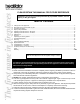
Please retain this manual for future reference Installation and service must be performed by a qualified installer, service agency or the gas supplier. Table of Contents A. B. C. D. E. F. G. H. I. J. K. L. M. N. O. P. Listings and Code Approvals............................................................................................................................................3 Description of the Imperial Gas Log Set....................................................................................
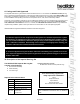
A. Listings and Code Approvals The Imperial Series Gas Log Set has been tested and listed in the U.S. in accordance with ANSI Z21.60-1996 (Gas Log Set). In Canada the Imperial Series Gas Log Set has been tested and approved in accordance with CGA 2.26-M96. It has been listed by Underwriters Laboratories Inc. for installation and operation in the United States and Canada as described in these Installation and Operating Instructions. All components are UL, AGA, CGA or CSA safety certified.
These gas log sets are available with different valve systems. The Fi36S, Fi36SL, Fi42S and Fi42SL sets use a separate regulator and valve system, and the Fi36M, Fi36ML, Fi42M and Fi42ML sets use a combination control with an intermittent pilot. Both valve systems are available in natural or propane gas. Only the “M” Series can be used with an optional remote control (RC-BATT-HTL). Conversion kits to convert from natural gas to propane or from propane to natural gas are available.
C. Important Information Installer: Please leave these instructions with the owner. Owner: Please retain these instructions for future reference. Important: Read these instructions carefully before making installation. • • • • • • • • • • This appliance must be installed only in a solid-fuel burning (woodburning) fireplace with a working flue and constructed of noncombustible materials.
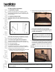
D. Step-by-Step Installation 1. Unpack the Log Set Carefully remove all parts from the shipping container. Your set includes four fiber logs, a burner assembly, the grate assembly, fire embers, lava rock, damper stop, and 10” flex connector. b. Remove the four screws that secure the top pan to the base of the appliance. See Figure 4. 2. Install the Damper Stop To install the damper stop: Open the damper to the fully open position and secure it open with the stop as shown in Figure 2.
f. Bleed the gas line to extract any air that may have been trapped inside the pipe. All connections must be tightened and checked for leaks with a commercially available, non-corrosive leak check solution. Be sure to rinse off the solution when done leak testing. DO NOT USE AN OPEN FLAME. Turn off the gas after the leak test. g. Reassemble the top pan with the four screws removed earlier, and the burner assembly with the four screws removed earlier.
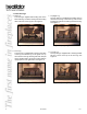
7. Place the Logs a. Rear Log The rear log is supplied with locating slots in the base of the log. Locate the rear log over the locating tabs at the rear of the top pan. See Figure 9. Figure 9 - Rear Log Placement Figure 11 - Top Right Log b. Front Log The front log is supplied with notches in the base of the log to locate the log on the grate. Line up the notches in the log with the grate bars and pull the log forward until it comes into contact with the upright portion of the grate bars. See Figure 10.
8. Intermittent Pilot Ignition a. Appliance Requirements: This appliance does not require 110VAC supply for operation. 1) A wiring diagram is shown in Figure 13. A battery pack is supplied with the appliance. This appliance requires the use of two D-cell batteries (not supplied with the appliance) for operation. 2) In the event of a power outage, the appliance will continue to operate if batteries are installed in the battery pack. Figure 13 - “M” Series Intermittent Pilot Wiring Diagram b.
E. Operating Instructions for the “M” Series FOR YOUR SAFETY READ BEFORE LIGHTING WARNING: If you do not follow these instructions exactly, a fire or explosion may result causing property damage, personal injury or loss of life. A. This appliance has an intermittent pilot. When lighting the pilot, follow these instructions exactly. C. B. BEFORE LIGHTING smell all around the appliance area for gas. Be sure to smell next to the floor because some gas is heavier than air and will settle to the floor.
F. Operating Instructions for the “S” Series FOR YOUR SAFETY READ BEFORE LIGHTING WARNING: If you do not follow these instructions exactly, a fire or explosion may result causing property damage, personal injury or loss of life. A. This appliance has a pilot which must be lit by hand. When lighting the pilot, follow these instructions exactly. B. BEFORE LIGHTING smell all around the appliance area for gas. Be sure to smell next to the floor because some gas is heavier than air and will settle to the floor.
G. Glass Doors If your fireplace is equipped with a glass door, the glass doors should be in the full open position when the appliance is operating. Operating the fireplace with the glass doors closed will block the radiant heat output of the fireplace and may cause incomplete combustion of the natural or propane gas fuel. Important! Always ensure that the wire fireplace screen is closed when the fireplace is operating. H. Cleaning Your gas logs require little care.
2. Possible Cures a. The damper needs to be opened further. b. The fireplace opening needs to be reduced by adding a drop panel across the top under the lintel. c. The air supply from outdoors needs to be increased. Open the outside air kit if the fireplace is so equipped, or crack open a door or window. d. If necessary, seek expert advice. Do not operate this appliance. 3.
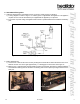
Fi36M Service Parts Diagram 36” Imperial Log set Beginning Manufacturing Date: N/A Ending Manufacturing Date: Active Replacement Parts - “S” Series 5 6 7 8 9 10 11 14 12 13 15 16 17 18 Log Set Assembly 3 1 4 2 Part number list on following page.
Fi36M Beginning Manufacturing Date: N/A Ending Manufacturing Date: Active Service Parts List 36” Imperial Log set IMPORTANT: THIS IS DATED INFORMATION. When requesting service or replacement parts for your appliance please provide model number and serial number. All parts listed in this manual may be ordered from an authorized dealer.
Fi42M Service Parts Diagram 42” Imperial Log set Beginning Manufacturing Date: N/A Ending Manufacturing Date: Active 5 6 7 8 9 10 11 14 12 15 13 16 17 18 Log Set Assembly 3 1 4 2 Part number list on following page.
Fi42M Beginning Manufacturing Date: N/A Ending Manufacturing Date: Active Service Parts List 42” Imperial Log set IMPORTANT: THIS IS DATED INFORMATION. When requesting service or replacement parts for your appliance please provide model number and serial number. All parts listed in this manual may be ordered from an authorized dealer.
N. Troubleshooting - “M” Series With proper installation and maintenance, your new decorative gas appliance should provide years of trouble-free service. If you do experience a problem, refer to the troubleshooting guide below. This guide will assist you or a qualified service technician in the diagnosis of problems and the corrective action to be taken. Symptoms 1 Pilot sparks, but will not light after repeated attempts. Possible Causes Corrective Action a. Main gas shutoff valve closed.
O. Troubleshooting - “S” Series Symptoms 1 Match will not light pilot. Possible Causes Corrective Action a. Main gas shutoff valve closed. Make sure that the shutoff valve located on the incoming gas line is open. b. Air in the gas line. Light a match. Turn valve knob to “PILOT” position and depress. Keep match near pilot burner until it lights. c. Valve knob is in “OFF” position Turn valve knob to “PILOT” position and depress. Keep match near pilot burner until it lights. d.
P. Accessory Parts (For “M” Series Only) The following accessory parts can be obtained from your dealer. The wireless remote control switch is supplied with installation instructions packaged with them. Should you need additional information please contact your dealer for more information or visit: www.hpba.org/staysafe.
Hearth & Home Technologies Inc. LIMITED LIFETIME WARRANTY Hearth & Home Technologies Inc., on behalf of its hearth brands (”HHT”), extends the following warranty for HHT gas, wood, pellet, coal and electric hearth appliances that are purchased from an HHT authorized dealer.
WARRANTY CONDITIONS: • • • • This warranty only covers HHT appliances that are purchased through an HHT authorized dealer or distributor. A list of HHT authorized dealers is available on the HHT branded websites. This warranty is only valid while the HHT appliance remains at the site of original installation. Contact your installing dealer for warranty service. If the installing dealer is unable to provide necessary parts, contact the nearest HHT authorized dealer or supplier.