+($7 &21752//(5 ,1& 5RRP $LU &RQGLWLRQHU AD-101A AD-81A ADS-81B CAUTION • BEFORE SERVICING THE UNIT, READ THE SAFETY PRECAUTIONS IN THIS MANUAL. • ONLY FOR AUTHORIZED SERVICE PERSONNEL.
Air Conditioner Service Manual TABLE OF CONTENTS Safety Precautions..........................................................................................................................................3 Dimensions .....................................................................................................................................................6 Outside Dimensions ...........................................................................................................................
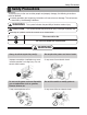
Safety Precautions Safety Precautions To prevent injury to the user or other people and property damage, the following instructions must be followed. Incorrect operation due to ignoring instructions will cause harm or damage. The seriousness is classified by the following indications. WARNING This symbol indicates the possibility of death or serious injury. CAUTION This symbol indicates the possibility of injury or damage to property only. Meanings of symbols used in this manual are as shown below.
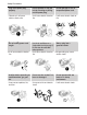
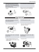
Safety Precautions Plug in the power plug properly. • Otherwise, it will cause electric shock or fire. Do not modify po power wer cord length. • It will cause electric shock or fire. Ventilate before operating air conditionerwhen gas goes out. • It may cause explosion, fire, and burn. 4 Room Air Conditioner Do not operate or stop the unit by inserting or pulling out the power plug. Do not damage or use an unspecified power cord. • It will cause electric shock or fire.
Safety Precautions If water enters the product, turn off the the power switch of the main body of appliance. Contact service center after taking the powerplug out from the socket. • It will cause electric shock or failure of machine. Do not clean the air conditioner with water. • Water may enter the unit and degrade the insulation. It may cause an electric shock. CAUTION Never touch the metal parts of the unit when removing the filter. Do not block the inlet or outlet.
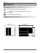
Dimensions Dimensions Symbols Used in this Manual This symbol alerts you to the risk of electric shock. This symbol alerts you to hazards that could cause harm to the air conditioner. NOTICE This symbol indicates special notes.
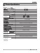
Specfications Product Specifications Specifications MODELS RAD-101A ITEMS 1Ø, 115, 60Hz POWER SUPPLY COOLING CAPACITY (Btu/h) INPUT (W) RUNNING CURRENT 9,800 1,000 9.3 (A) (BTU/W.h) 9.8 9. 8 OPERATING INDOOR ( C) 26.7(DB)* 26.7(DB)* CONDITION OUTDOOR ( C) E.E.R REFRIGERANT (R-22) CHARGE 19.4(WB)** 19.4(WB) ** 35(DB)** 35(DB) 23.9(WB)** 23.9(WB) ** 410g(14.5oz) EVAPORATOR Ø 7.0, 3ROW 14STACKS CONDENSER Ø7.
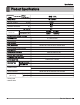
Specfications Product Pr oduct Specifications Specifications MODELS RAD - 81A ITEMS 1Ø, 115, 60Hz POWER SUPPLY COOLING CAPACITY (Btu/h) INPUT (W) RUNNING CURRENT (A) (BTU/W.h) E.E.R OPERATING INDOOR ( C) CONDITION OUTDOOR ( C) REFRIGERANT (R-22) CHARGE EVAPORATOR 26.7(DB)* 26.7(DB)* 19.4(WB)** 19.4(WB) ** 35(DB)** 35(DB) 23.9(WB)** 23.9(WB) ** 260 g(9.2 oz) Ø5.
Specfications Product Pr oduct Specifications Specifications MODELS RADS - 81B ITEMS 1Ø, 115, 60Hz POWER SUPPLY COOLING CAPACITY (Btu/h) INPUT (W) RUNNING CURRENT (A) (BTU/W.h) E.E.R OPERATING INDOOR ( C) CONDITION OUTDOOR ( C) REFRIGERANT (R-22) CHARGE EVAPORATOR 26.7(DB)* 26.7(DB)* 19.4(WB)** 19.4(WB) ** 35(DB)** 35(DB) 23.9(WB)** 23.9(WB) ** 490 g(17.3 oz) Ø5.
Installation Installation Select the Best Location CAUTION: All side louvers of the cabinet must remain exposed on the outdside of the structure. OUTSIDE FENCE AWNING HEAT RADIATION 30"-60" 1. To prevent vibration and noise, make sure the unit is installed securely and firmly. 2. Install the unit where the sun does not shine directly on the INSIDE unit. 3.
Installation How to Install INNER SILL Window Requirements NOTICE All supporting parts should be secured to firm wood, masonry, or metal. 1. This unit is designed for installation in standard double hung windows with actual opening widths of 22" to 36". The upper and lower sash must open sufficiently to allow a clear vertical opening of 15" from the bottom of the sash to the window stool. 2.
Installation PREPARATION OF CHASSIS Shipping Screws 1. Remove the screws which fasten the cabinet at both sides and at the back. 2. Slide the unit from the cabinet by gripping the base pan handle and pulling forward while bracing the cabinet. 3. Cut the window sash seal to the proper length. Peel off the backing and attach the Foam-Pe to the underside of the window sash. 4. Remove the backing from the top Upper Guide FoamPe and attach it to the bottom of the Upper Guide. 5.
Installation 3. Loosely assemble the Sill Support using the parts in Figure 7. INDOOR OUTDOOR Sill Support Bolt Nut Figure 7 4. Select the position that will place the Sill Support near the outer most point on sill (See Figure 8) 5. Attach the Sill Support to the cabinet track hole in relation to the selected position using 2 Type A screws in each support(See Figure 8). 6. The cabinet should be installed with a very slight tilt(about 1/2") downward toward the outside (See Figure 9).
Installation 10. Slide the unit into the cabinet.(See Figure 11) CAUTION: For security purpose, reinstall screws (Type A) at cabinet's sides. Power cord Screw(Type A) Screw(Type A) 11. Cut the Foam-Strip to the proper length and insert between the upper window sash and the lower window sash. (See Figure 12) Figure 11 Foam-Strip Figure 12 12. Attach the Window Locking Bracket with a Type C screw. (See Figure 13) Window Locking Bracket 13.
Operation Operation • • • • • • DESIGNED FOR COOLING ONLY POWERFUL AND INCREDIBLE COOLING TOP-DOWN CHASSIS FOR THE SIMPLE INSTALLATION AND SERVICE BUILT-IN ADJUSTABLE THERMOSTAT WASHABLE ONE-TOUCH FILTER COMPACT SIZE Location and Function of Controls CAUTION: If you turn off the air conditioner or switch from cooling to the fan, wait at least 3 minutes before setting to cooling again. Operation O ff Me d Fa n Low Fa n High C ool Me d C ool Low C ool - Turns air conditioner off.
Operation Remote Control Operations CAUTION: The Remote Controller will not function properly if strong light strikes the sensor window of the air conditioner or if there are obstacles between the Remote Controller and the air conditioner. The controls look like this: Controls Power 1 7 3 Temp 2 Fan Speed 3 Timer Mode Energy Saver Auto Swing 6 4 5 4 5 6 2 1 1. Power • To turn the Set ON, push the button. To turn the Set OFF, push the button again.
Disassembly Disassembly — Before the following disassembly, POWER SWITCH set to OFF and disconnect the power cord. Mechanical Parts 1. FRONT GRILLE 1. Open the lnlet grille upward or downward. 2. Remove the screw which fastens the front grille. 3. Pull the front grille from the right side. 4. Remove the front grille. 5. Re-install the component by referring to the removal procedure, above.(See Figure 17) Figure 17 2. CABINET 1.
Disassembly Air Handling Parts 1. AIR GUIDE AND BLOWER 1. Remove the front grille. 2. Remove the cabinet. 3. Remove the control box. 4. Remove the 3 screws which fasten the brace. 5. Remove the brace. 6. Remove the 2 screws which fasten the evaporator. 7. Move the evaporator forward and pulling it upward slightly. (See Figure 20) 8. Move the evaporator to the left carefully. 9. Pull out the hook of orifice by pushing the tabs and remove it. (See Figure 21) 10.
Disassembly 3. MOTOR 1. Remove the cabinet. 2. Remove the evaporator. 3. Remove the orifice. 4. Remove the blower. 5. Remove the fan. 6. Remove the control box cover and housing of the motor in the control box. 7. Remove the 2 screws which fasten the motor from the mount motor. (See Figure 23) 8. Remove the motor. 9. Re-install the components by referring to the removal procedure, above.(See Figure 23) Figure 23 Electrical Parts 1. OVERLOAD PROTECTOR 1. Remove the cabinet. 2.
Disassembly 3. CAPACITOR MODEL : ROTARY SWITCH TYPE MODEL 1. Remove the control box. 2. Remove the knobs and the screw which fasten control panel from control box. 3. Remove the screw which is located in the front. 4. Open the bottom side of control box. 5. Remove the screw and the clamp which fasten the capacitor. 6. Disconnect all the leads of capacitor terminals. 7. Re-install the components by referring to the removal procedure, above.
Disassembly 6. ROTARY SWITCH MODEL : ROTARY SWITCH TYPE MODEL 1. Remove the control box. 2. Open the control box. 3. Remove the 2 screws which fasten the rotary switch. 4. Disconnect all the leads of the rotary switch terminals. 5. Remove the rotary switch. 6. Re-install the components by referring to the above removal procedure. (See Figure 29) 7. POWER CORD 1. Remove the control box. 2. Open the control box. 3. Disconnect the grounding screw from the control box. 4. Disconnect the 2 receptacles. 5.
Disassembly 2. EVAPORATOR 1. Remove the cabinet. 2. Remove the 2 screws which fasten the evaporator. 3. Move the evaporator sideways carefully. 4. After discharging the refrigerant completely, unbraze the interconnecting tube at the evaporator connections. 5. Remove the evaporator carefully. 6. Re-install the component by referring to notes. (See Figure 32) 3. CAPILLARY TUBE 1. Remove the cabinet. 2. After discharging the refrigerant completely, unbraze the interconnecting tube at the capillary tube. 3.
Disassembly Equipment needed: Vacuum pump, Charging cylinder, Manifold gauge, Brazing equipment. Pin-off tool capable of making a vapor-proof seal, Leak detector, Tubing cutter, Hand Tools to remove components, Service valve.
Schematic Diagram Schematic Diagram Wiring Diagram MODEL : ROTARY SWITCH TYPE MODEL P OWE R INP UT B K (B R ) WH(B L) (P lain) (R ibbed) 1 R OT AR Y S WIT C H 4 7 8 L RD RD 5 6 H BK BK 3 4 M BL BL 1 2 G N(G N/Y L) 2 OR (B R ) MOT OR G N(G N/Y L) BL YL C AP AC IT OR YL OR (B R ) 6 F C BK BK RD RD B R (Y L) B L BL R C OMP . 3 S C OLP THE R MOS TAT H BK RD 8 5 P .T.C WIR ING DIAG R AM 3854AR 3563A 7 S: Service Parts N: Non Service Parts LOCATION NO.
Schematic Diagram Circuit Diagram MODEL : TOUCH & REMOTE CONTROL TYPE MODEL 1 6 2 4 7 5 3 8 LOCATION NO. DESCRIPTION Q'TY PER SET 1 POWER CORD ASSEMBLY 1 2 FAN MOTOR 1 3 COMPRESSOR 1 4 DISPLAY P.W.B ASSEMBLY 1 5 MAIN P.W.
Schematic Diagram Electronic Control Device 26 Room Air Conditioner
Schematic Diagram Components Location(For Main P.W.
Troubleshooting Guide Troubleshooting Guide Piping System CONDENSER COIL FAN CAPILLARY TUBE MOTOR COMPRESSOR BLOWER EVAPORATOR COIL Figure 38 is a brief description of the important components and their function in what is called the refrigeration system. This will help you to understand the refrigeration cycle and the flow of the refrigerant in the cooling cycle.
Troubleshooting Guide Troubleshooting Guide In general, possible trouble is classified in two kinds. The one is called Starting Failure which is caused from an electrical defect, and the other is ineffective Air Conditioning caused by a defect in the refrigeration circuit and improper application. Unit runs but poor cooling. Ineffective Cooling Check cold air circulation for smooth flow. Check outdoor coil (heat exchanger) and fan operation. Dirty indoor coil (heat exchanger) Check gas leakage.
Troubleshooting Guide Fails to Start Check of power source. Check of circuit breaker and fuse. Check of control panel setting. Check control panel. Compressor fails only to start. Fan only fails to start. Drop of power voltage. Defect of compressor capacitor. Capacitor check. Improper thermistor setting Loose terminal connection Improper wiring Improper wiring. Defect of fan motor capacitor. Irregular motor resistance (Ω) Irregular motor insulation (Ω) Replacement. Replacement of fan motor.
Troubleshooting Guide ■ MODEL : BG8000ER, WG8000RY4, WG1000RY4 ELECTRIC PARTS TROUBLESHOOTING GUIDE: Possible Trouble 1 Is the Trans input power AC 115V? • The unit does not operate. NO • Check the Fuse. • Check the wiring diagram. YES Is the Trans output power about AC 14V? NO YES Is output Voltage of IC01D DC 12V? Is shorted the Trans. output? YES NO NO • Check the Main P.W.B pattern. • Exchange the Trans. • Exchange D02D~D05D. • Exchange IC01D.
Troubleshooting Guide Possible Trouble 2 • The compressor does not operate. Is Temp. NO setting set lower than Room Temp.-0.5°C? • Set the Temp. setting to lower Temp. YES Is the voltage No.10 of IC01M 0V? NO Is the voltage N0.7 of IC01M DC 5V? NO YES YES • Check the RY-COMP. • Check the wiring Diagram. • Exchange IC01M. Is the Unit for 3 minutes delay? NO YES • Wait 3 Minutes • Exchange MAIN P.W.B Ass'y.
Troubleshooting Guide • Romote controller does not operate. Possible Trouble 5 Is the voltage of Battery about over 2.3V? NO • Exchange the battery. YES Is the voltage No.16 of CN-DISP1 on Main P.W.B Ass'y DC 5V? NO • Check the P.W.B pattern. YES NO Is the connection of CN-DISP1 all right? • Connect connector to CN-DISP1 exactly. YES • Exchange Receiver Ass'y. Possible Trouble 6 Is the IC01G all right? • It displays abnormally on Display P.W.B Ass'y. NO • Exchange IC01G.
Troubleshooting Guide ROOM AIR CONDITIONER VOLTAGE LIMITS NAME PLATE RATING MINIMUM MAXIMUM 115V ± 10% 103.5V 126.5V COMPLAINT Fan motor will not run. CAUSE REMEDY No power Check voltage at outlet. Correct if none. Power supply cord Check voltage to rotary switch. If none, check power supply cord. Replace cord if circuit is open. Rotary switch Check switch continuity. Refer to wiring diagram for terminal identification. Replace switch if defective.
Troubleshooting Guide COMPLAINT Fan motor noise. Compressor will not run, fan motor runs. CAUSE REMEDY Fan If cracked, out of balance, or partially missing, replace it. Blower If cracked, out of balance, or partially missing, replace it. Loose set screw Tighten it. Worn bearings If knocking sounds continue when running or loose, replace the motor. If the motor hums or noise appears to be internal while running, replace motor. Voltage Check voltage. See the limits on the preceding page.
Troubleshooting Guide COMPLAINT Compressor cycles on overload. Compressor cycles on overload. Insufficient cooling Excessive noise 36 Room Air Conditioner CAUSE REMEDY Voltage Check the voltage. See the limits on the preceding page. If voltage is not within these limits, call an electrician. Overload Check overload, if externally mounted. Replace if open. (If the compressor temperature is high, remove the overload, cool, and retest.) Fan motor If not running, determine the cause.
Exploded Vie w 554030 554031 749740 731273 559010 267110 W52106-2 W52106-1 249950 249950 263230 266003 269310 W0CZZ W0CZZ 268712 137215 352115 552102 552113 238310 352113 146812 135500 264110 149410 264110 237200 268714 135510 135500 35211A
Replacement Parts List PART NO LOCATION NO DESCRIPTION 130410 130910 135312 135313 135500 749740 147581 147582 149980 152302 237200 238310 249950 264110 263230 267110 268712 268714 BASE ASSEMBLY,SINGLE CABINET ASSY,SINGLE GRILLE ASSY,FRONT(SINGLE) GRILLE ASSY,INLET COVER,CONTROL(INDOOR) UPPER GUIDE CABINET LOUVER,HORIZONTAL LOUVER,VERTICAL SHROUD FILTER(MECH),A/C PANEL,CONTROL ESCUTCHEON CONTROL BOX ASSEMBLY,SINGLE POWER CORD ASSEMBLY THERMISTOR ASSEMBLY REMOTE CONTROLLER PWB(PCB) ASSEMBLY,DISPLAY PWB(P
6SHFLILFDWLRQV DQG SHUIRUPDQFH GDWD VXEMHFW WR FKDQJH ZLWKRXW QRWLFH +($7 &21752//(5 ,1& :(//:257+ $9(18( -$&.