WHP - Water Source Heat Pump Design, Installation & Operations Manual Revision 02A
WattMaster WHP Installation & Operations Manual Section 1.................................................................................... Design Guide Section 2................................................................... Installation and Wiring Section 3....................................................................................Programming Section 4....................................................... Start-Up and Troubleshooting This document is subject to change without notice.
Section 1 Table of Contents Conventions ..................................................................... 1 General Information......................................................... 2 Water Source Heat Pump Units .......................................................................................2 Water Source Heat Pump Systems ..................................................................................3 WattMaster WHP Control System...........................................................
WattMaster WHP Section 1 Conventions This document uses the following definitions throughout as a guide to the user in determining the nature of the information presented: Note: Additional information which may be helpful. Tip: Suggestion to make installation, set-up, and troubleshooting easier. Caution: Items which may cause the equipment not to function correctly but will not otherwise damage components. Warning: Errors which can result in damage to equipment and void warranties.
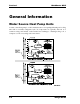
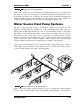
Section 1 WattMaster WHP General Information Water Source Heat Pump Units A water source heat pump is a self-contained water-cooled packaged heating and cooling unit with a reversible refrigerant cycle. Its components are typically enclosed in a common casing, and include a tube-in-tube heat exchanger, a heating/cooling coil, a compressor, a fan, a reversing valve and controls.
WattMaster WHP Figure 1-1: Section 1 Typical Water Source Heat Pump During the cooling mode, the tube-in-tube heat exchanger functions as a condenser and the coil as an evaporator. In heating mode, the tube-in-tube heat exchanger functions as an evaporator and the coil as a condenser. A reversing valve is installed in the refrigerant circuit permitting changeover from heating to cooling, and vice versa. The condenser and evaporator tubes are designed to accept hot and cold refrigerant liquid or gas.
Section 1 WattMaster WHP accommodate changes in location and sizes as thermal zones or zone occupancy change. This system is often installed in ceiling plenums, which frees up valuable floor space. Another valuable benefit of water source heat pumps is that they can accommodate simultaneous calls from zones requiring heating or cooling. Depending on the climate, outside air may require preheat or cooling prior to being introduced to the unit.
WattMaster WHP Section 1 Pump Reset and Aux. Heating or Cooling. An internal seven day schedule and holiday schedule functions are also built into each WHP Controller. With the WHP system the sometimes complex control requirements of a large water source heat pump system can be handled with an off the shelf controls system that has most of the features of a full blown building automation system but at a much lower cost.
Section 1 WattMaster WHP WHP Sequence of Operation HVAC Mode of Operation There are four possible modes of operation. These are Cooling Mode, Heating Mode, Vent Mode, and the Off Mode. The HVAC mode of operation is calculated the same way in both occupied and unoccupied modes of operation. Off Mode The schedule is off and no overrides are active. There is no heating or cooling demand in the space. Under these conditions, all outputs will be off and the analog output will be set to 0.0 vdc.
WattMaster WHP Section 1 Occupied/Unoccupied Mode of Operation Since the WHP contains its own built in Real Time Clock, it can operate from its own internal scheduling system. This schedule supports two Start & Stop events per day and up to 14 Holiday periods. The Holidays all use the same special Holiday Start/Stop times programmed by the user. If the current operating mode is unoccupied, the WHP can accept a push-button override back to the occupied mode.
Section 1 WattMaster WHP HVAC Operation w/ Reversing Relay If the user has configured the WHP to control a Reversing Valve and a Compressor, the following sequence of operation occurs during a heating or cooling demand. Note: If you configure the WHP to look for a proof of flow Enable signal from the Loop Controller then the following sequence assumes a request was made by the WHP during a demand condition and that the Loop Controller gave permission for the WHP to start its compressor.
WattMaster WHP Section 1 HVAC Operation w/ Heat/Cool Relays If the user has configured the WHP to control Individual Heating and Cooling relays the following sequence of operation occurs during a heating or cooling demand. NOTE: If you configure the WHP to look for a proof of flow Enable signal from the Loop Controller then the following sequence assumes a request was made by the WHP during a demand condition and that the Loop Controller gave permission for the WHP to operate its heating or cooling.
Section 1 WattMaster WHP WHP Loop Controller Sequence of Operations Summary The Water Source Heat Pump Loop Controller waits for a Request to Run signal from a Heat Pump or from a Binary Contact Closure. Once the request is received the Loop Controller activates a Pump to initiate water flow to the Heat Pumps. Once the pump is activated and proof of flow has been determined, a Global is broadcast to all Heat Pumps to enable them to go ahead and run their compressors.
WattMaster WHP Section 1 pump exceeds the first pumps run time by the same amount. This keeps both pumps with roughly the same number of hours on each pump. Changeover occurs at the time the run time setpoint is exceeded. The running pump is shut off at the same time the standby pump is energized, this prevents any down time or alarms. The unit can be configured to control either the Loop Inlet temperature or the loop outlet temperature.
Section 1 WattMaster WHP Heat Rejection Control If the compressor is not running, no heat rejection can be active. If any heat rejection is still active when the compressor is turned off, the heat rejection will be immediately removed, without regard to any minimum run or off times. Heat rejection cannot be active at the same time as heat addition, so any heat addition is removed or staged off before the heat rejection can be started. A maximum of 8 stages of heat rejection can be controlled.
WattMaster WHP Section 1 Staged Heat Addition Heat Addition is staged up based on a different deadband level for each stage. Basically, if the user programmed a 2° deadband, then the first stage could activate at the setpoint, stage 2 would activate 2° below the setpoint, stage 3 would activate 4° below the setpoint, etc... Staging down is calculated in the same manner, except the water temperature would need to increase above the setpoint by the deadband amount.
Section 1 WattMaster WHP Water Temperature Alarming The controlling water temperature is monitored to prevent it from exceeding both a user defined High and Low Alarm Limit. If either limit is exceeded for a user defined length of time, an alarm is generated and the compressor output is de-activated. If the high limit is exceeded, the heat addition outputs are de-activated and if the low limit is exceeded, the heat rejection outputs are de-activated.
Section 1 WattMaster WHP COMPUTER (OPTIONAL) RS-485 Comm Loop Room Sensor 32K 8K COMM T SHLD R LD4 with Optional Override & Adj. RAM 485 COMM EPROM REC.
Section 1 WattMaster WHP Notes: 1-16 Design Guide
Section 2 Table of Contents Tips Before Beginning Installation.................................. 1 Communications Loops ................................................... 3 Communications Loop Wiring Overview....................................................4 WHP Loop Controller ....................................................... 6 WHP Loop Controller Addressing .................................... 9 Supply & Return Water Temperature Sensors .............. 10 Outside Air Temperature Sensor..........
Section 2 Table of Figures Figure Figure Figure Figure Figure Figure Figure Figure Figure Figure Figure Figure Figure Figure Figure Figure Figure Figure 2-1: System Overview ........................................................................................2 2-2: Communication Loop Wiring, Daisy-Chain Configuration .......................4 2-3: WHP Loop Controller.................................................................................6 2-4: WHP Loop Controller Wiring .........................
WattMaster WHP Section 2 Tips Before Beginning Installation Take a few moments to review the following before beginning installation of the WattMaster WHP System. • Familiarize yourself with all system components and review all documentation. Pay special attention to “Cautions” and “Warnings” since these may keep you from experiencing unnecessary problems. • Before installing controllers, be sure to tag it with its appropriate location.
Section 2 WattMaster WHP COMPUTER (OPTIONAL) RS-485 Comm Loop Room Sensor 32K 8K COMM T SHLD R LD4 with Optional Override & Adj. RAM 485 COMM EPROM REC.
WattMaster WHP Section 2 Communications Loops The Communications Loop is two wire shielded RS-485. The loop is best connected in daisy chain configuration, meaning the loop is connected from one controller to another. It is not necessary to sequentially address the WHP Controllers in relation to their location on the loop. Cable must be Belden No. 82760 or equivalent. Tip: Incorrect wiring of the communications loop is the most common mistake made during installation.
Section 2 WattMaster WHP Communications Loop Wiring Overview 03/31/04 03:38PM WED OCCUPIED NO ALARMS COMPUTER (OPTIONAL) POWER 24VAC GND COMMUNICATIONS T SHLD R RS-485 SYSTEM MANAGER POWER SUPPLY YS101716 REV. 1 SYSTEM MANAGER COMM LINK II INTERFACE (SET TO MULTIPLE LOOP) UNIT COMES WITH STANDARD WALL MOUNT 120/24 VAC POWER SUPPLY ( MAY ALSO BE POWERED FROM 24VAC ) Remote Link (OPTIONAL) 32K 8K COMM LD4 U2 CX2 U1 RLY1 D2 RN3 U6 RN2 (1 MEG) YS101816 REV.
WattMaster WHP Section 2 The daisy chain is the best method for running a communications loop since there is only one starting point and one ending point for each of the communications loops. Even though the daisy chain configuration is preferred, the star configuration can also be used. If required, a combination of the two can also be used. Remember, the best communication loop wiring is the one which utilizes the minimum number of ends while using the shortest wiring path.
Section 2 WattMaster WHP WHP Loop Controller The WHP Loop Controller may be installed in any convenient protected location. It is recommended that the loop controller be mounted indoors in a secure location, that is not subject to extremes in temperature or moisture. .20 Dia. Typ. of 4 6.2’’ D1 4.0” 1 CX3 C21 U3 CX1 RN1 CX2 U2 U1 CX4 RLY1 U4 V1 D2 TB1 COMM V2 T TB 2 SHLD RLY2 V3 U5 PAL RS-485 (1 MEG) YS101816 REV.
WattMaster WHP Section 2 CX2 U2 U1 CX4 RLY1 U4 V1 D2 TB1 COMM V2 T SHLD RLY2 V3 U5 PAL RS-485 COMM RLY3 RN3 (1 MEG) YS101816 REV. 2 U6 D4 LD8 LED1 TUC-5R PLUS HH RN2 1 +VREF C2 C3 R28 PU3 CX8 L1 D14 D12 R13 JP1 SC1 C13 C12 U13 R15 U12 CX14 C14 R19 C16 U14 CX13 TB4 C15 D19 GND D16 C19 C18 D18 PJ3 PJ2 EXPANSION 7824CT PRESSURE SENSOR 24VAC Required VA For Transformer Loop Controller = 8VA Min.
Section 2 WattMaster WHP Warning: Polarity is very important when connecting power to the controllers! The grounded side of the control transformer must be connected to the terminal labeled GND on the controller. If a single transformer is used to power more than one controller you must connect GND-toGND and 24VAC-to-24VAC on each controller. Failure to observe polarity will result in damage to one or more components in your system.
WattMaster WHP Section 2 WHP Loop Controller Addressing The WHP Loop Controller must be set for address #30. See address setting instructions for the WHP Loop Controller that follow. A maximum of 29 WHP Controllers are allowed on the loop that contains the WHP Loop Controller. All other loops may have 30 WHP Controllers.
Section 2 WattMaster WHP Supply & Return Water Temperature Sensors Sensors for monitoring supply and return water temperature are available in two main types, fluid immersion temperature sensors (See Figure 2-6) and strap-on sensors (See Figure 2-7). Both are 0-10000 ohm thermistor type sensors. The fluid immersion sensor generally has better accuracy than the strap-on type but either is suitable for typical water source heat pump temperature requirements.
WattMaster WHP Section 2 The strap-on type sensor has a brass housing that senses the water temperature through contact with the exterior surface of the pipe. The sensor should be mounted in contact with the underside of the pipe in order to insure accurate temperature readings. The sensor assembly is secured to the pipe by using the supplied wire ties to wrap and secure the sensor to the pipe. Thermal conductive compound is also supplied to insure a good thermal connection with the pipe.
Section 2 WattMaster WHP Outside Air Temperature Sensor The outside air sensor must be located where it will not be affected by direct sun or heat producing equipment. Mounting under the eve of a roof is often a good choice. Caution: Complaints of inaccurate outside sensor readings are very common and can almost always be shown to be the result of poor sensor location. Note: All temperature sensors supplied with the system utilize the same thermistor type sensing element.
WattMaster WHP Section 2 CommLink II Interface The CommLink II Interface provides for communications between the MiniLink communication interfaces installed on the system. The CommLink II is required for proper communications, even if a PC is not used. Locate the CommLink II near the computer or modem if they are installed on the system. The cable connections between the CommLink II and the computer or modem should be kept to less than twenty-five feet.
Section 2 WattMaster WHP WHP Controller The WHP Controller may be installed in any convenient protected location. Observe the recommended environmental limitations for the WHP Controller when selecting a installation location. The environmental limitations are a temperature range of 10°F to 149°F, and a maximum operating humidity of 90% RH non-condensing. The WHP Controller may be mounted by fastening to a flat surface through the mounting plate. The unit is mounted by four (4) screws in the corners.
WattMaster WHP Section 2 All Comm Loop Wiring Is Straight Thru T SH R T SH R T SH R T SH R Connect To Next Controller And/Or MiniLink On WHP Controller Local Loop RS-485 9600 Baud COMM T SHLD R Room Sensor Water Source Heat Pump Unit Connections E P R O M R A M RELAY OUTPUTS LD4 TMP W A R M E R NORMAL C O O OVR L E R REC. GND AUX Connection To AUX Terminal is Reqd Only When Sensor Is Specified With Slide Adjust Option Discharge Air Temp.
Section 2 WattMaster WHP The WHP Controller requires the following electrical connections: 18 Gauge minimum unless otherwise noted. -24VAC Supply Voltage........................................................................... 2 Conductors -Communications Loop ...................................... 2 Conductor twisted pair with shield (WattMaster Cable, Belden #82760 or equivalent) -Discharge Air Temperature Sensor .................................. (24 ga. Min.
WattMaster WHP Section 2 WHP Controller Addressing NOTE: IGNORE ANY MARKINGS OR NUMBERS ON THE SWITCH USE THE CHART! To determine the boards address, add the values of all the switches which are toggled down in the direction of the arrow NOTE: ADDRESS 30 CANNOT BE USED ON THE LOOP THAT HAS THE WHP LOOP CONTROLLER ATTACHED. ADDRESS 30 ON THAT LOOP IS RESERVED FOR THE WHP LOOP CONTROLLER.
Section 2 WattMaster WHP MiniLink Addressing Connect To Next MiniLink And/Or CommLink On Network Loop MiniLink Communications Interface Network Loop RS-485 19200 Baud ADD 1 T NETWORK SH R 2 4 8 16 32 OFF > All Communication Loop Wiring Is Straight Through T SH R T SH R T SH R 24VAC T SH R Line Voltage 24VAC GND T LOOP SH R Local Loop RS-485 9600 Baud Required VA For Transformer MiniLink = 6VA Min. See Note 1.
WattMaster WHP Section 2 Room Sensors The room sensor uses a patented flush mount design to isolate the temperature sensing element from the housing which mounts flush with the wall surface. Room sensors should be located on an inside wall away from direct sunlight or heat producing equipment such as computers, copiers, etc. Such devices can adversely affect the accuracy of the sensor.
Section 2 WattMaster WHP Connect the terminal labeled GND on the zone sensor to the terminal labeled GND on the WHP Controller Analog Input terminal block. Connect the terminal labeled TMP on the zone sensor to the terminal labeled AIN 1 on the WHP Controller Analog Input terminal block. If the zone sensor has a setpoint adjust slider, then connect the sensor terminal labeled AUX to the WHP Controller AIN 2 terminal block.
WattMaster WHP Section 2 Supply Air Temperature Sensor The supply air temperature sensor should be located in the duct, as close to the rooftop unit discharge as possible for best response. Locate the sensor in the center of the widest part of the duct. Use the supplied template and a 5/16" drill to make a hole for the sensor. Install the gasket over the probe and mount securely to the duct using the supplied sheet metal screws. Be sure the gasket is compressed to provide an air tight seal.
Section 2 WattMaster WHP Leaving Water Temperature Sensors The leaving water temperature sensor (optional) when used should be located on the leaving water piping close to the water source heat pump unit. Either a thermowell type or a surface mount sensor may be used depending on job requirements. Leads Are Non-polarized. Butt Splice Leads To 24 Gauge Wire Minimum. Connect Leads To "Analog In" And "Ground" At Controller. 1/8-27 NPT External Thread 1/8-27 NPSM Internal Thread 1/2" NPT External Thread 5.
Section 3 Table of Contents LCD/Keypad Operations................................................... 1 System Manager Layout...................................................................................................2 Keypad Functions ............................................................................................................2 System Manager LED Indicators .....................................................................................3 Heat Pump Status Screens..................
WattMaster WHP Section 3 LCD/Keypad Operations Main Screen Heat Pump v1.xx Tuesday Operations 04/13/04 09:15 AM Outdoor Air 58.7°F The Water Source Heat Pump System Manager is the operator’s interface to the status and setpoints of any WattMaster Water Source Heat Pump (WHP) component on your communications loop. With the System Manager, you can view any temperature or output condition and change any setpoint to fine tune the operations of the total system.
Section 3 WattMaster WHP System Manager Layout Heat Pump v2.11 Wednesday Operations 7/21/04 04:35 PM Outdoor Air 85.6° Keypad Functions The System Manager keypad is labeled either numerically or as to actual function for that key. Below is a summary of the labeled keys and their functions.
WattMaster WHP Section 3 System Manager LED Indicators There are two LED indicators located on the right hand side of the System Manager. The top LED indicates an Alarm condition if the Manager detects an alarm condition while polling the system. The bottom LED is active during actual communications or packet transfers. This LED will normally “flicker” and not remain on constantly.
Section 3 WattMaster WHP Heat Pump Status Screens View Status Only Status Only View [ Enter Unit ID# ] Selected Unit: 101 By selecting the View Status Only menu item, you can access any heat pump or the loop controller and read all available temperatures, outputs, and operating conditions for the selected unit. No passcode is required to access these status screens, and no setpoints are available to the user from these screens. To access a unit, enter the Unit ID you wish to view.
WattMaster WHP Section 3 If you selected menu item #1 View Status Only and you entered the Unit ID of an installed WHP Controller, the following Status Screens are available. Status Screen #1 WSHPRV 1 V2.03 Space Temp.:xxx.x°F CSP xx.x° HSP xx.x° Slide Adjust: x.x°F Line 2 - Current Zone Temperature Line 3 - Current Cooling Setpoint ( CSP ) and Heating Setpoint ( HSP ) Line 4 - Effect of optional Sensor Slide Adjustment on the current operating setpoints.
Section 3 WattMaster WHP Status Screen #3 WSHPRV 1 V2.03 Occupied Mode Fan Status...: ON Operations Enabled Line 2 - Current Operating Status Unoccupied Mode Occupied Mode Pushbutton Override Forced Occupied Forced Unoccupied Forced Fan Only Mode Line 3 - Current Fan Status Fan Start Delay! ON OFF Line 4 - Current Enable Status from Loop Controller Operations Disabled Operations Enabled Status Screen #4 WSHPRV 1 V2.03 Compressor...
WattMaster WHP Section 3 Status Screen #6 WSHPRV 1 V2.03 Space Temp Sensor OK Filter OK Cooling Failure Line 2 - Line 3 Line 4 - Bad Space Sensor Hi Space Temp Alarm! Lo Space Temp Alarm! Space Temp Sensor OK Dirty Filter Alarm Filter OK Cooling Failure! Heating Failure! Note: If no alarms exist, then the screen displays the message shown for No Alarms! If ANY alarm exists then the three lines display one of the messages shown above.
Section 3 WattMaster WHP View Alarms Alarm Address Locations SYSTEM ALARM STATUS Alarm @ Unit ID 118 The System Manager can be programmed to poll all the units on your heat pump system for alarm information. This allows the centrally located System Manager to display an Alarm Indicator whenever an alarm condition exists anywhere on your system. The actual alarms are not displayed on this screen, only the Unit ID where the alarm is located.
WattMaster WHP Section 3 Menu Setpoints Full Setpoint Access 1) 2) 3) 4) Set Time & Date Access Units New Passcodes Rebuild Alarm Map If you selected the Menu key from the first menu screen you can access all setpoints available from any unit on your system. You must be a Level 2 user to access these setpoints. If you haven’t already been asked to enter the passcode, you will be asked before the Full Setpoint Access menu is displayed.
Section 3 WattMaster WHP Programming Date Program Time/Date Month (1-12): 4 Day (1-31): 18 Year (00-99): 04 Month - Enter the Month (1 to 12) Day - Enter the Day of the Month (1 to 31) Year - Enter the current Year with 2 digits (00 to 99) Daylight Savings Adjustments Daylight Savings Adjustments Enabled Use Left/Right Arrow If your area of the country requires Daylight Savings changes, you can enable the System Manager to automatically reset its own clock during the Daylight Savings changeover.
WattMaster WHP Section 3 New Passcodes Programming Passcodes Enter Level Level [Must New Passcode 1....: XXXX 2....: XXXX Be 4 Digits] The System Manager has two levels of passcode. Level 1 users are limited to viewing Setpoints and Alarms only. Level 2 users have complete system access. Any status or setpoint field can be read or reset from WHP System Manager. The default passcode is “1111” for level 1 and “2222” for level 2.
Section 3 WattMaster WHP Rebuild Alarm Map Rebuilding Screens Clearing Old Map .................... ................ Build New Map? (ESC = NO) Building New Map Loop: 1 Unit: 1 Dec) Go To Next Loop ESC) Abort Process Alarm Unit Map Built Press Any Key To Continue If you would like the LED Alarm Indicator to function on the front of your System Manager, you must enable Alarm Polling by building an Alarm Map.
WattMaster WHP Section 3 Heat Pump Setpoints Heat Pump Setpoint Menu 1) WHP Setpoints 2) WHP Schedules 3) Reset Pumps ESC) To Exit From the main menu screen select MENU on the keypad, select MENU again for Setpoints. Then select “Access Units” (keypad #2) and finally enter the loop and zone number for the desired unit. As the screen above shows, there are three areas of programming available for each WHP Controller.
Section 3 WattMaster WHP Setpoint Screen #2 WHP #1 Setpoints Unoccupied Setpoints Cool Setup.: xx°F Heat SetBk.: xx°F The Unoccupied Heating and Cooling Setbacks are programmed on this screen. The Cooling SetUp is added to the Occupied Cooling Setpt to create the Unoccupied Cooling Setpoint. The Heating SetBack is added to the Occupied Heating Setpt to create the Unoccupied Heating Setpt.
WattMaster WHP Section 3 Setpoint Screen #5 WHP #1 Setpoints Min Run Time: x Min Min Off Time: x Min Min Cycle...:xx Min The Min Run Time determines how long the compressor must remain on once it has been activated. The Min Off Time determines how long the compressor must remain off once it is de-activated. The Min Cycle time determines how many times per hour the compressor can be started. If you entered 10 minutes, the compressor could start a maximum of 6 times in a one hour period.
Section 3 WattMaster WHP Setpoint Screen #8 WHP #1 Setpoints WHP Configuration R/VALVE & COMPRESSOR Use Left/Right Arrow If your heat pump uses a reversing valve to determine the heating or cooling mode of operation, select the message R/VALVE & COMPRESSOR. If you are controlling separate stages of heating and cooling select the INDIVIDUAL STAGING message.
WattMaster WHP Section 3 Setpoint Screen #11 WHP #1 Setpoints Relay5 Configuration AUXILIARY RELAY MODE Use Left/Right Arrow If your system is configured to use the reversing valve and you only have one stage of heating and cooling, that last relay becomes available for other uses. The AUXILIARY RELAY MODE can be used to operate the relay manually from the Prism computer front end program.
Section 3 WattMaster WHP Setpoint Screen #14 WHP #1 Setpoints Heat Pump Scheduling Uses Schedule #: x 0) Int. 1-7) Clock The Heat Pump Controller can use the internal time clock for a setting an occupied schedule, for this the setpoint will be 0. It can also be programmed to follow an external schedule command. You must have an OSS Optimal Start Scheduler installed somewhere on you communications loop to provide the external schedule, and you select the schedule number here.
WattMaster WHP Section 3 Setpoint Screen #17 WHP # 1 Setpoints Heat Stage #2 SAT Lockout: 60°F This setpoint is to shut the heating off when the supply air temperature is too warm. When the supply air temperature is above this setpoint, it will prevent the second stage of heat from coming on. Minimum Default Maximum 30°F 60°F 200°F Max Effect Setpoint Screen #18 SENSOR CALIBRATION SPC xxx.x° xxxx.x°° SAT xxx.x°° xxxx.x°° WAT xxx.x°° xxxx.
Section 3 WattMaster WHP 2) WHP Schedules The Water Source Heat Pump controllers contain their own built in scheduling capability for calculating Occupied/Unoccupied periods. Select item #2 from Schedules menu to access the following schedule programming menu. Schedule Menu WSHP Schedules 1) Week Schedules 2) Holidays MENU) Previous Menu Week Schedule Programming Event #1 WEEK SCHEDULES Sunday Event #1 Start Time..: xxxx Stop Time..: xxxx Event #2 WEEK SCHEDULES Sunday Event #2 Start Time..
WattMaster WHP Section 3 Holidays Holiday Day Selection There are 14 Holiday periods available, organized as a Start Day / Stop Day event. If the Holiday only lasts one day, enter the same date for the Start & Stop days. There is no limit to the duration or number of days that can be included in one holiday, other than it cannot extend past December 31st. If you have a holiday that crosses the end of year border, you will need to use two holiday periods to accomplish this event.
Section 3 WattMaster WHP 3) Reset Pumps WSHPRV 1 v2.03 Tripped Pump Reset Reset Mode: Disabled Use Left/Right Arrow If one of your heat pumps has tripped off, it can be manually reset from the following screen. You will have entered the Unit ID to access the WHP Menu screen, so that is the unit that will receive this reset command. If you don’t want to send the command, select the Disabled message with the arrow keys.
WattMaster WHP Section 3 Loop Controller Status Loop Controller Status Menu 1) View Status Only 2) View Alarms Menu) Setpoints ESC) To Exit From the main menu screen select MENU on the keypad. Then select “View Status Only” (keypad #1) and finally enter the loop and zone number for the desired unit. As the screen above shows, there are two areas of status available for the Loop Controller. Menu item #1 accesses all the status screens for the Loop Controller.
Section 3 WattMaster WHP Status Screen #2 Loop Control v1.06 No Call to Run Water Flow Proved! LOOP ENABLED Line 2 - Current operating Mode: No Call To Run ACTIVE CALL TO RUN FREEZE PROTECTION! Line 3 - Current Water Flow Status: Water Flow Proved! No Flow Detected Line 4 - Current Request to Operate Status: LOOP ENABLED LOOP DISABLED Status Screen #3 Loop Control v1.
WattMaster WHP Section 3 Status Screen #5 Cool Cool Cool Cool Stage Stage Stage Stage # # # # 5.: 6.: 7.: 8.: OFF OFF OFF OFF Line 1 - Cool/Heat Stage #5 On/Off Line 2 - Cool/Heat Stage #6 On/Off Line 3 - Cool/Heat Stage #7 On/Off Line 4 - Cool/Heat Stage #8 On/Off Status Screen #6 Loop Control v1.06 Pressure.: xxx.x PSI Pump VFD.: xx.x VDC Heat VFD.: xx.
Section 3 WattMaster WHP Status Screen #7 Loop Control v1.06 Line 2 - Pump Failure or Blank Line Line 3 - Hi Control Water Temp No Alarms! Lo Control Water Temp Line 4 - Fire/Smoke Alarm Phase Shutdown Note: If no alarms exist, then the screen displays the message shown for No Alarms! If ANY alarm exists, then the three lines display one of the messages shown above.
WattMaster WHP Section 3 Loop Controller Setpoints Loop Controller Setpoint Menu 1) LC Setpoints 2) LC Schedules 3) LC Force Modes ESC) To Exit Setpoint Screen #1 WHP Loop Setpoints HEAT REJECTION Setpoint......: xx°F Stage Deadband: xx°F If the controlling water temperature rises above this Setpoint, the Heat Rejection or Cooling Stages begin to stage on. As the temperature continues to rise above the Setpoint by the Deadband amount, an additional stage is added.
Section 3 WattMaster WHP Setpoint Screen #3 WHP Loop Setpoints HEATING ADDITION Setpoint......: xx°F Stage Deadband: xx°F If the controlling water temperature drops below this Setpoint, the Heat Addition or Boilers begin to stage on. As the temperature continues to drop below the Setpoint by the Deadband amount, an additional stage is added. Each additional stage can only activate if the temperature drops below the Setpoint by the number of active stages times the deadband value.
WattMaster WHP Section 3 Setpoint Screen #6 WHP Loop Setpoints Water Hi Limit: xx° Water Lo Limit: xx° Alarm Delay...: xM If the controlling water temperature rises above the Water Hi Limit setpoint, all heat addition will be removed and one stage of heat rejection will be activated. If the controlling water temperature drops below the Water Lo Limit setpoint, all heat rejection stages will be removed and one heat addition stage will be activated.
Section 3 WattMaster WHP Setpoint Screen #9 WHP Loop Setpoints Lead/Lag Changeover Switch After xxx Hrs The two pumps will switch after this programmed amount of time so that each pump accumulates roughly the same number of run time hours. If a pump is currently running and this time period is exceeded, the changeover will occur as soon as pump run time exceeds the setpoint. The current pump will shut off and the standby pump will start at the same time.
WattMaster WHP Section 3 Setpoint Screen #12 WHP Loop Setpoints Isolation Valves Set Open if PSI is Above Hi Limit...: xxx PSI If you configured the system for Variable Speed Pumping with a Pressure Sensor for proof of flow, the Loop Controller can send a signal to all the Heat Pumps to open their Isolation Valves whenever a Hi Limit Pressure is exceeded. If the Heat Pumps do not control an Isolation Valve, then the only reaction is to reduce the variable speed pump voltage signal.
Section 3 WattMaster WHP Notes: 3-32 Programming
Section 4 Table of Contents 1.0 Communications Overview........................................ 1 1.1 How It Works...........................................................................................................1 1.2 WattMaster WHP System ........................................................................................1 2.0 WHP Controller Overview .......................................... 4 2.1 How It Works...................................................................................
Section 4 5.0 Troubleshooting ...................................................... 21 5.1 General Troubleshooting........................................................................................21 5.1.1 Communications Troubleshooting Checklist.................................................21 5.1.2 General Troubleshooting Checklist ...............................................................22 5.2 Alarms............................................................................................
WattMaster WHP Section 4 1.0 Communications Overview Perhaps no other portion of the system seems as difficult to diagnose as the communications loop, yet it really can be quite simple if you understand how it works. In fact, much of the troubleshooting can be done by simple observation. We will lead you through the system functions and then provide you with detailed instructions for checking each piece of equipment. 1.
WattMaster WHP Section 4 COMPUTER (OPTIONAL) RS-485 Comm Loop Room Sensor 32K 8K COMM T SHLD R LD4 with Optional Override & Adj. RAM 485 COMM EPROM REC.
WattMaster WHP Section 4 All communications wiring should be labeled to avoid confusion and to aid future servicing. 03/31/04 03:38PM WED OCCUPIED NO ALARMS COMPUTER (OPTIONAL) POWER 24VAC GND COMMUNICATIONS T SHLD R POWER SUPPLY RS-485 SYSTEM MANAGER YS101716 REV.
WattMaster WHP Section 4 2.0 WHP Controller Overview 2.1 How It Works 2.1.1 Initialization On system powerup the COMM LED remains extinguished for five seconds. After this delay, the COMM LED will blink out the address of the controller (Address Switch Setting). The COMM LED will then extinguish for another five seconds and then begin to blink for a twenty second startup delay. At the conclusion of this twenty second period, the COMM LED will begin blinking a diagnostic code every ten seconds.
WattMaster WHP 2.2 Section 4 Becoming Familiar with the WHP Controller COMMUNICATIONS DRIVER CHIP RAM PIN 1 INDICATION EPROM RAM SIZE SELECT JUMPER PAL 32K 8K RS-485 COMMUNICATIONS LOOP COMM T SHLD R LD4 COMMUNICATIONS LED RAM 485 COMM EPROM REC. ADDRESS SWITCH ( ADDRESS 18 SHOWN ) CPU ANALOG INPUTS Leaving Water Temp or Dirty Filter Lockout ADDRESS ADD 24 VAC Common for Inputs 1 - 3 Fan-On/Off Rev. Valve-On/Off (Heat 1) Compressor-On/Off (Heat 2) Heat Pump Reset (Cool 1) Aux.
WattMaster WHP 2.2.2 Section 4 Analog Inputs This connector carries the analog and binary control input signals. AIN1 - Space Temp - This input accepts a two wire 10K Type III thermistor temperature sensor. The sensor measures 10,000 Ohms @ 77°F. The resistance drops as the temperature increases. The sensor is connected between this terminal and the GND terminal. This input is also monitored for push-button override commands.
WattMaster WHP Section 4 OUT3 - Compressor or Heat 2 - This output enables the compressor if you have configured the WHP Controller for a compressor and reversing valve configuration. If the WHP Controller is configured for individual staging of heating and cooling (no reversing valve) then this output enables heating stage 2. OUT4 - Heat Pump Reset or Cool 1 - This output can be used to reset a compressor that has gone off line.
WattMaster WHP 2.2.
WattMaster WHP Section 4 3.0 Loop Controller Overview 3.1 How It Works 3.1.1 Initialization On system powerup LED2 remains extinguished for five seconds. After this delay, the LED2 will blink out the address of the controller (Address Switch Setting). The LED2 will then extinguish for another five seconds and then the LED2 will begin blinking a diagnostic code every ten seconds. This code is described in the troubleshooting section.
WattMaster WHP Section 4 3.2 Loop Controller Inputs & Outputs 3.2.1 Analog Inputs AIN1 - Return Water Temp - This input accepts a two wire 10K Type III thermistor temperature sensor. The sensor measures 10,000 Ohms @ 77°F. The resistance drops as the temperature increases. The sensor is connected between this terminal and the GND terminal. AIN2 - Supply Water Temp - This input accepts a two wire 10K Type III thermistor temperature sensor. The sensor measures 10,000 Ohms @ 77°F.
WattMaster WHP 3.2.3 Section 4 Binary Output R1 – Compressor Enable – Energizes the first stage of cooling. R2 – Main Pump – Energizes the lead water pump. R3 – Standby Pump – Energizes the standby pump if the main pump fails to start. R4 – Alarm Indicator – Energizes when an alarm occurs on the Loop Controller. R5 – Not Used – This output is not used. COM 1-3 - Common – 24 VAC from the AHU is connected to this terminal and is the common for inputs 1 through 3.
WattMaster WHP 3.2.6 Section 4 Comm Connector - Communications RS-485 Communications Connector - This connector provides the connection point for the Local Loop RS-485 communications loop. The wiring consists of a twisted pair of wires with a shield. T - RS-485 (+) Communications terminal SHLD - Common return wire, this point is internally tied to GND on the WHP Controller. R - RS-485 (-) Communications terminal 3.2.
WattMaster WHP Section 4 Connect To Next Controller And/Or MiniLink On Local Loop Local Loop RS-485 9600 Baud (See Note 3).
WattMaster WHP Section 4 4.0 Start-Up 4.1 Blink Codes for WHP Controllers The WHP Controller uses an on board LED to indicate various diagnostic conditions during powerup and operation. The WHP Unit LED is labeled “COMM”.
WattMaster WHP 4.2 Section 4 Blink Codes for Loop Controllers The Loop Controller uses an on board LED to indicate various diagnostic conditions during powerup and operation. The Loop Controller Unit LED is labeled “LED2”. Starting with power up the LED blink codes are as follows: • • • • Off for five seconds COMM LED blinks the board address (Address 14 = 14 blinks) Five second pause Status code is repeatedly blinked every ten seconds to indicate controller status: Priority No.
WattMaster WHP 4.4 Section 4 Installation and Commissioning Information Familiarize yourself with the installation manual and system wiring diagrams before installing! 1. Check to see if you have all the correct components for your installation. 2. Establish the location for the CommLink Interface first. This is where your communication cable will begin. 3. Layout your communication wiring. For systems with more than 30 WHPs or more than one MiniLink, there are multiple communication loops: A.
WattMaster WHP Section 4 10. Install CommLink and power-up. At this point you are ready to begin commissioning the system. It is preferred, though not necessary, to use a PC with Prism software to assist in the commissioning process. 11. Start with the first controller on the communication loop or in multiple loop systems; start with the MiniLink or with the System Manager. Plug in the Communication terminal then plug in the Power terminal. 12.
WattMaster WHP Section 4 03/31/04 03:38PM WED OCCUPIED NO ALARMS COMM LINK II INTERFACE (MULTIPLE LOOP) POWER 24VAC GND COMMUNICATIONS T SHLD R RS-485 SYSTEM MANAGER POWER SUPPLY YS101716 REV. 1 SYSTEM MANAGER 32K 8K COMM LD4 RN1 CX2 U2 U1 RLY1 GND D2 V2 RLY3 COMM ( 1 MEG) YS101816 REV. 2 RN3 U6 D4 TUC-5R PLUS HH RN2 R4 C2 RN4 CX8 R10 D12 R13 SC1 PWR GND 24VAC AOUT1 4 ANALOG IN MOD I/O BD.
WattMaster WHP Section 4 4.5 Setting Address Switches 4.5.
WattMaster WHP 4.5.2 Section 4 Loop Controller Addressing The Loop Controller address should always be set for address #30. A maximum of 29 WHP Controllers on the loop that contains the Loop Controller. All other loops may have 30 WHP Controllers. (Refer to Figure 2-10 for more detail) 4.5.
WattMaster WHP Section 4 5.0 Troubleshooting 5.1 General Troubleshooting The following is a guide to assist in troubleshooting the WattMaster WHP System. It is provided as a systematic approach to determining and resolving common system problems. 5.1.1 Communications Troubleshooting Checklist No WHP or Loop Controller Units are Communicating • • • • • • • • • • Is the CommLink II connected and plugged in? Is the CommLink II installed, a single or multiple loop version.
WattMaster WHP 5.1.2 Section 4 General Troubleshooting Checklist Begin troubleshooting by locating the general problem in the list below. Detailed component troubleshooting information follows later in this section. Zone is too warm • • • • Is zone calling for cooling? Is the compressor disabled due to minimum off time setting? Is water proof of flow signal disabled? Is the LED blinking an error code? See Figure 4-6.
WattMaster WHP Section 4 5.2 Alarms When an alarm occurs in the WHP or Loop Controller, it is reported to the System Manager. The alarms cause the light on the System Manager to illuminate. The View Alarms screen will indicate the address of the alarms. The Status screen will display the type of alarm that has occurred. Here is a list of the alarms that are reported to the System Manager.
WattMaster WHP Section 4 5.3 Checking Comm. Loop Voltages 5.3.1 Checking the CommLink II Network Loop Diagram Overview This test checks for proper Network loop voltages at the CommLink II. The Loop LED (located on the front panel) should “flicker” when the CommLink II is attempting to communicate. The Loop LED will flicker more noticeably for a few seconds when first powered up. If the Loop LED does not flicker, the unit is defective. Make sure CommLink II jumper is set to “Multi” position.
WattMaster WHP 5.3.2 Section 4 Checking the Comm Loop at the CommLink II Diagram The indicated values are typical of a normal system, actual readings may deviate slightly due to the number of units connected and other system specific factors. Note: All of the connected Minilinks should be powered up for this test. Overview This is a “quick check” to determine if any of the driver chips on the Network loop are damaged. Since all units will “float” both of their communications connections at about 2.
WattMaster WHP 5.3.3 Section 4 Checking the CommLink II Driver Diagram Overview This test checks for proper Network loop voltages coming from the CommLink II. The Loop LED (located on the front panel) should “flicker” when the CommLink II is attempting to communicate. The Loop LED will flicker more noticeably for a few seconds when first powered up. If the LED does not flicker, the unit is not functioning. Proper loop voltages are essential for reliable communications.
WattMaster WHP 5.3.4 Section 4 Checking the MiniLink Network Loop Diagram Meter Set To Read DC Volts The indicated readings are typical of a normally operating system. Actual readings may vary slightly due to the number of units installed and other factors. Any significant deviation from these values generally indicates a problem. Note: These tests assume that the CommLink II is connected and powered, and that all MiniLinks which are connected are also powered.
WattMaster WHP 5.3.5 Section 4 Checking the MiniLink Network Driver Diagram Meter Set To Read DC Volts Note: These tests assume that the MiniLink being checked is powered up Overview This check is intended to determine if the Network Comm Driver chip on a MiniLink is damaged. Before unplugging the Network loop from the MiniLink, observe the Network Loop LED (located near the connector). It should periodically “flicker” as the CommLink II requests data from the MiniLink.
WattMaster WHP 5.3.6 Section 4 Checking the MiniLink Local Loop Diagram Meter Set To Read DC Volts The indicated readings are typical of a normally operating system. Actual readings may vary slightly due to the number of units installed and other factors. Any significant deviation from these values generally indicates a problem. Note: These tests assume the MiniLink is powered up Overview Proper loop voltages are essential for reliable communications.
WattMaster WHP 5.3.7 Section 4 Checking the Local Loop at MiniLink Diagram Meter Set To Read DC Volts The indicated values are typical of a normal system. Actual readings may deviate slightly due to the number of units connected and other system specific factors Note: These tests assume that the controllers being checked are powered up. Overview This is a “quick check” to determine if any of the WHP Controllers or WHP Loop Controller on a Local Communications Loop are damaged.
WattMaster WHP 5.3.7 Section 4 (continued) Action Condition Action If voltages are too high or too low on either side 1. One or more of the attached controllers has a damaged Comm Driver chip. Locate and replace the driver chip(s). See "1.3.11 Comm Driver Chip Replacement”. 2. Wiring errors such as "crossed connections", short circuits, etc.
WattMaster WHP 5.3.8 Section 4 Checking the MiniLink Local Loop Driver Diagram Meter Set To Read DC Volts The indicated values are typical of a normal operating system. Actual readings may deviate slightly. Note: These tests assume that the MiniLink is powered up. Overview This test checks for proper Local Loop voltages coming from the MiniLink. The Local Loop LED (located near the connector) should “flicker” when the MiniLink is operating and when first powered up.
WattMaster WHP 5.3.9 Section 4 Checking the Local Loop at a WHP Controller Diagram Meter Set To Read DC Volts The indicated readings are typical of a normal operating system. Actual readings may vary slightly due to the number of units installed and other factors. Any significant deviation from these values generally indicates a problem. Note: These tests assume that a MiniLink is connected and powered up. Overview Proper loop voltages are essential for reliable communications.
WattMaster WHP Section 4 5.3.10 Checking WHP Controller Driver Chip Diagram Meter Set To Read DC Volts Note: These tests assume that the controller being checked is powered up. Overview This check is intended to determine if the Comm Driver chip on a controller is damaged. Damage typically occurs when the communications loop is exposed to excessive voltage, as may occur during installation, due to wiring errors. The driver chips are socketed on all boards to facilitate servicing.
WattMaster WHP Section 4 5.4 Troubleshooting Loop Controller 5.4.1 Checking the Loop Controller Analog Inputs Diagram Overview The analog input wiring can be checked at the Loop Controller by checking voltages on the Analog Input Connector. SET METER TO READ DC VOLTS + - + 12V R AIN1 AIN2 - AIN3 AIN4 AIN5 GND GND ALL READINGS ARE TAKEN WITH THE (-) LEAD OF THE METER ON THE GND TERMINAL AOUT1 AOUT2 AIN7 GND If any of the RWT, SWT, OAT inputs read greater than 5.
WattMaster WHP 5.4.1 Section 4 (continued) AIN4 1.9 volts (100°F) - 3.6 volts (40°F) Outdoor Air Temp Typical is 2.5 volts @ 77°F AIN5 If the input is OPEN, the voltage will be greater than 5.0 volts Manual Reset If the input is CLOSED, the voltage will be less than 0.5 volts AIN7 If the input is OPEN, the voltage will be greater than 5.0 volts Phase Loss If the input is CLOSED, the voltage will be less than 0.5 volts AIN1-Exp. Bd. If the input is OPEN, the voltage will be greater than 5.
WattMaster WHP 5.4.2 Section 4 Checking the Loop Controller Outputs Diagram Overview The analog output wiring can be checked at the Loop Controller by checking voltages on the Analog Output Connector. SET METER TO READ DC VOLTS - Note: + R + ALL READINGS ARE TAKEN WITH THE (-) LEAD OF THE METER ON THE GND TERMINAL - The Loop Controller must be powered for these tests.
WattMaster WHP 5.4.3 Section 4 Checking the Local Loop at a WHP Loop Controller Diagram Meter Set To Read DC Volts The indicated readings are typical of a normal operating system. Actual readings may vary slightly due to the number of units installed and other factors. Any significant deviation from these values generally indicates a problem. Note: These tests assume that a MiniLink is connected and powered up. Overview Proper loop voltages are essential for reliable communications.
WattMaster WHP 5.4.4 Section 4 Checking WHP Loop Controller Driver Chip Diagram Meter Set To Read DC Volts Note: These tests assume that the controller being checked is powered up. Overview This check is intended to determine if the Comm Driver chip on a controller is damaged. Damage typically occurs when the communications loop is exposed to excessive voltage, as may occur during installation, due to wiring errors. The driver chips are socketed on all boards to facilitate servicing.
WattMaster WHP 5.4.5 Section 4 Comm Driver Chip Replacement MINILINK COMMUNICATIONS INTERFACE WHP CONTROLLER PIN 1 T SH R NETWORK LOOP COMMUNICATIONS DRIVER CHIP (U5) Ys101806 REV.
WattMaster WHP 5.5 Temperature Sensor Resistance Chart TEMPERATURE ºF -10 -5 0 5 10 15 20 25 30 35 40 45 50 52 54 56 58 60 62 64 66 68 69 70 71 72 73 74 75 76 78 80 Section 4 RESISTANCE Ω* 93333 80531 69822 60552 52500 45902 40147 35165 30805 27140 23874 21094 18655 17799 16956 16164 15385 14681 14014 13382 12758 12191 11906 11652 11379 11136 10878 10625 10398 10158 9711 9302 VOLTAGE AT TEMPERATURE 4.620 4.550 4.474 4.390 4.297 4.200 4.095 3.982 3.862 3.737 3.605 3.470 3.330 3.275 3.217 3.160 3.
WattMaster WHP 5.6 Section 4 Pressure Sensor Voltage Chart PRESSURE PSI MILIAMPS CURRENT VOLTAGE AT INPUT VDC* PRESSURE PSI MILIAMPS CURRENT VOLTAGE AT INPUT VDC* 0 1 2 3 4 5 6 7 8 9 10 11 12 13 14 15 16 17 18 19 20 21 22 23 24 25 26 27 28 29 30 31 32 33 4.00 4.32 4.64 4.96 5.28 5.60 5.92 6.24 6.56 6.88 7.20 7.52 7.84 8.16 8.48 8.80 9.12 9.44 9.76 10.08 10.40 10.72 11.04 11.36 11.68 12.00 12.32 12.64 12.96 13.28 13.60 13.92 14.24 14.56 1.00 1.08 1.16 1.24 1.32 1.40 1.48 1.56 1.64 1.72 1.
WattMaster WHP Section 4 Notes: Start-Up and Troubleshooting 4-43
Form: WM-WHP-IO-02A Printed in the USA October 2004 All rights reserved Copyright 2004 Wattmaster Controls Inc. • 8500 NW River Park Drive • Parkville MO • 64152 E-mail: mail@wattmaster.