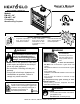
Owner’s Manual Installation and Operation Models: EM-415 - 36” EM-485T - 42” Circulating Wood Burning Fireplace DO NOT DISCARD THIS MANUAL Important operating • and maintenance instructions included. Read, understand and follow these instructions for safe installation and operation. WARNING • Leave this manual with party responsible for use and operation.
Read this manual before installing or operating this fireplace. Please retain this owner’s manual for future reference. Congratulations! Congratulations on selecting a Heat & Glo wood burning fireplace. The Heat & Glo fireplace you have selected is designed to provide the utmost in safety and reliability. This owner’s manual should be retained for future reference. We suggest you keep it with your other important documents and product manuals.
•! • • • Safety Alert Key: DANGER! Indicates a hazardous situation which, if not avoided will result in death or serious injury. WARNING! Indicates a hazardous situation which, if not avoided could result in death or serious injury. CAUTION! Indicates a hazardous situation which, if not avoided, could result in minor or moderate injury. NOTICE: Indicates practices which may cause damage to the fireplace or to property.
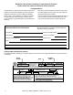
Warranty Hearth & Home Technologies Inc. LIMITED LIFETIME WARRANTY Hearth & Home Technologies Inc., on behalf of its hearth brands (”HHT”), extends the following warranty for HHT gas, wood, pellet, coal and electric hearth appliances that are purchased from an HHT authorized dealer.
WARRANTY CONDITIONS: • • • • This warranty only covers HHT appliances that are purchased through an HHT authorized dealer or distributor. A list of HHT authorized dealers is available on the HHT branded websites. This warranty is only valid while the HHT appliance remains at the site of original installation. Contact your installing dealer for warranty service. If the installing dealer is unable to provide necessary parts, contact the nearest HHT authorized dealer or supplier.
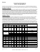
1 Listing and Code Approvals A. Appliance Certification This fireplace system has been tested and listed in accordance with UL 127 and ULC-S610 standards by Underwriters Laboratories Inc. for installation and operation in the United States and Canada. This fireplace may be installed in sleeping rooms EXCEPT in manufactured homes. If installed with a gas log set, provisions for the National Fuel Gas Code must be met.
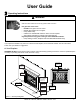
User Guide 2 Operating Instructions WARNING HOT SURFACES! Glass and other surfaces are hot during operation AND cool down. Hot glass will cause burns. • DO NOT touch glass until it is cooled • NEVER allow children to touch glass • Keep children away • CAREFULLY SUPERVISE children in same room as fireplace. • Alert children and adults to hazards of high temperatures. High temperatures may ignite clothing or other flammable materials. • Keep clothing, furniture, draperies and other flammable materials away.
B. Seasoned Wood D. Grate Properly seasoned wood is important for successful operation of your fireplace. Most woodburning fireplace problems are caused by burning wet, unseasoned wood. This fireplace is designed to be used with the grate supplied with this unit or one approved by HHT. The grate will break down over time and will need occasional replacement. Seasoned firewood is wood that is cut to size, split and air dried to a moisture content of around 20%.
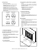
H. Glass Doors K. Vented Gas Log Sets & Gas Log Lighters • • • • Glass doors are optional. Refer to Figure 2.2 for how to properly use them. WARNING! Risk of Fire! Install ONLY doors approved by Hearth & Home Technologies, Inc. WARNING! Risk of Fire and Smoke! Fireplaces equipped with doors should be operated only with doors fully open or doors fully closed. If doors are left partly open, gas and flame may be drawn out of the fireplace opening. FULLY OPEN CORRECT PARTLY OPEN INCORRECT Optional.
N. Wood Fuel Seasoned Wood Hardwood vs Softwood Your fireplace performance depends on the quality of the firewood you use. • • • • • • • Seasoned wood contains about 8,000 BTUs per pound . Hard woods are more dense than soft woods. Hard woods contain 60% more BTUs than soft woods. Hard woods require more time to season, burn slower and are harder to ignite. Soft woods require less time to dry, burn faster and are easier to ignite.
3 Maintenance and Service B. Chimney Inspection/Cleaning A. Disposal of Ashes Frequency: When they reach bottom of grate By: Homeowner Warning! Risk of Fire! Ashes could contain hot embers. • • • Place ashes in a metal container with a tight-fitting lid. The closed container should be placed on a noncombustible floor or on the ground, well away from all combustible materials, pending final disposal.
C. Check Firebox Refractory Frequency: After each ash removal By: Homeowner Warning! Risk of Fire! Inspect fireplace refractory. Crumbling, deteriorated refractory can allow overheating of surrounding materials. Expansion and contraction will cause minor cracking of the refractory. This is normal. The refractory will require periodic replacement depending on use.
4 Troubleshooting Guide Start Fire Problems Possible Cause Solution Can’t get fire started Excessive smoke or spillage Burns too slowly Smolders, sizzles Not enough kindling/paper or no kindling/paper Use dry kindling, more paper. Arrange kindling & wood for air movement. Damper closed/not fully open Open damper. Not enough air for fire to ignite Check for restricted cap/shroud. Open air kit (if installed). Check for flue blockage.
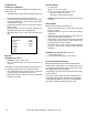
Installer Guide 5 Getting Started A. Typical Fireplace System Additional lateral support for chimney above roof (or enclosed in chase) if needed (Section 8) NOTICE: • Illustrations and photos reflect typical installations and are for design purposes only. • Illustrations/diagrams are not drawn to scale. • Actual product may vary from pictures in manual.
B. Design and Installation Considerations D. Negative Pressure Notice: Check building codes prior to installation. Warning! Risk of Asphyxiation! Negative pressure can cause spillage of combustion fumes and soot. Fire must draft properly for safe operation. • Installation MUST comply with local, regional, state and national codes and regulations.
E. Locating Fireplace & Chimney Location of the fireplace and chimney will affect performance. • • • • • • Install through the warm airspace enclosed by the building envelope. This helps to produce more draft, especially during lighting and die-down of the fire. Penetrate the highest part of the roof. This minimizes the effects of wind loading. Locate termination cap away from trees, adjacent structures, uneven roof lines and other obstructions. Minimize the use of chimney offsets.
F. Tools and Supplies Needed H. Inspect Fireplace and Components Before beginning the installation be sure the following tools and building supplies are available: Warning! Risk of Fire and/or Explosion! Damaged parts could impair safe operation. Do NOT install damaged, incomplete or substitute components. Keep fireplace dry.
6 Framing & Clearances A. Select Fireplace Location F Note: 3/4 in. (19 mm) min. air space from fireplace to combustible materials. 1/2 in. (13 mm) allowed at nailing flanges. G E B A B Across a corner C In an exterior chase or projecting into a garage Note: In addition to these framing dimensions, also reference the following sections: • Clearances (Section 6.B.) • Mantel Projections (Sections 11.E. & 11.F.) • Fireplace Dimensions (Section 13.A.
B. Clearances Warning! Risk of Fire! You must comply with all minimum air space clearances to combustibles as specified in Figure 6.2. Do NOT pack required air spaces with insulation or other materials. Storm Collar of) (ro Roof Flashing Shaded areas represent 2 in. (51 mm) min. air space clearance required around pipe (attic) Attic Insulation Shield (insulation) (ceiling) Offset/Return (secured with hanger straps) 2 in. (51 mm) min. (ceiling) Must have 2 in.
C. Sidewalls/Surrounds • • Adjacent combustible sidewalls must be located a minimum of 12 in. (305 mm) (may be 24 in) from the fireplace opening. Combustible and non-combustible mantel legs, surrounds and stub walls may be constructed per Figure 6.3. Grid represents 1 in. scale FLUSH FRONT BRICK FRONT 39 °a EM-415 EM-485 A 50 °a ng l e 10 3/4 in. [273 mm] Model # 4 in. [102 mm] A Fireplace Opening B Outside Dimensions 36 914 42 1067 42 1067 48 1219 in. mm in. mm 9 3/4 in.
7 Installation of Fireplace Caution! Risk of Cuts/Abrasions. Wear protective gloves and safety glasses during installation. Sheet metal edges are sharp. A. Things to Consider • • • • Location of chimney air kit (see Figure 7.4) Location(s) of outside air kit Electrical connections and/or wall switch Gas line piping B. Position the Fireplace • • Place the fireplace on a continuous flat surface. Follow framing instructions in Section 6.
3 ft min. from top of uppermost chimney section to air inlet. )))))))))) )))) ) )))))))))))))))))))))))) )))))))))))))))))))))))))) )) ) )) ) ) ) )))) )))))))))))))))) ) ) )) Note: Chimney air kit not shown, but required in Canada. Figure 7.3 Possible Outside Air Inlet Locations NO Outlet blocked by snow, leaves, etc.
E. Install Outside Air Kit • • • • • • Keep duct runs short and straight to minimize restriction. A small dip is acceptable for a cold air trap. The outside air kit must be installed on the left hand side of the fireplace. Locate the air inlet in a clear area, preferably into prevailing wind during the heating season. Refer to Figure 5.2. Install as shown in Figures 7.3, 7.4 and 7.5. The air duct may be run vertically. The outside air inlet must be at least 3 ft (.
Bend this half tab down 90 degrees Figure 7.6 Bend this tab down 90 degrees Prepare Junction Box Bracket Slide the flanges of the junction box through the slots in the bracket. Figure 7.9 Figure 7.7 Attach the Heat Shield Position Bracket on Junction Box Bend remaining half tab down 90 desgrees. Figure 7.10 Attach the Junction Box Figure 7.8 Secure Bracket to Junction Box G. Installation of Fan Follow installation instructions supplied with fan kit.
8 Chimney Assembly Notice: Chimney performance may vary. • Trees, buildings, roof lines and wind conditions affect performance. • Chimney height may need adjustment if smoking or overdraft occurs.
A. Chimney Requirements Measure vertical distances from the base of the fireplace as shown in Figure 8.2. • Minimum overall straight height 16.5 ft • Minimum height with offset/return 16.5 ft (5.03 m) 90 ft (27.43 m) • Maximum chimney length between an offset and return 20 ft (6.1 m) • Maximum distance between chimney stabilizers 35 ft (10.67 m) • Double offset/return minimum height 20 ft (6.1 m) 6 ft (1.83 m) 35 ft (10.67 m) 6 ft (1.
B. Using Offsets/Returns • • Use an offset/return to bypass overhead obstructions. An offset and return can be used as a single entity or separated by chimney section(s). Warning! Risk of Fire! Do not use offset/returns greater than 30°. Chimney draft will be restricted and could cause overheating and fire. • • • • Measure the shift needed to avoid the overhead obstruction. Refer to dimension A in Figure 8.3. Find the appropriate A dimension listed in Table 8.2.
C. Assembling Chimney Sections D. Install Chimney Air Kit Warning! Risk of Fire! Do NOT install substitute or damaged chimney components. • • • Use only those components described in this manual. Substitute or damaged chimney components could impair safe operation and cause overheating and fire. E. Installing Ceiling Firestops • • • Support the pipe during construction and check to be sure inadvertent loading has not dislodged the chimney section from the fireplace or at any chimney joint.
F. Installing Attic Insulation Shield Warning! Risk of Fire! You MUST install an attic insulation shield when there is any possibility of insulation or other combustible material coming into contact with the chimney. • Do NOT pack insulation between the chimney and the attic insulation shield. • Failure to keep insulation and other materials away from chimney pipe could cause fire. • Do NOT offset chimney inside insulation shield.
G. Cut out Hole in Roof • • • • • • • Refer to Figure 8.9. Plumb from roof to center of chimney. Drive a nail up through roof to mark center of pipe. Measure to either side of nail and mark the 14-1/2 in. x 14-1/2 in. (368 mm x 368 mm) opening required. Measure opening on the horizontal; actual length may be larger depending on roof pitch. Cut out and frame opening. Refer to Chapter 25 of the Uniform Building Code for roof framing details. H.
J. Chimney Termination Requirements • Install a cap approved and listed for this fireplace system. Locate cap where it will not become plugged by snow or other materials. Locate cap away from trees or other structures. The bottom of the termination cap must be at least 3 ft (.91 m) above the roof AND at least 2 ft (.61 m) above any portion of roof within 10 ft (3.05 m) as shown in Figure 8.10. The distance required between caps is shown in Figure 8.10. Slanted Roofs Chimney must extend 2 ft (.
9 Chase Installations A. Construct the Chase A chase is a vertical boxlike structure built to enclose the fireplace and/or its vent system. Vertical chimneys that run on the outside of a building must be installed inside a chase. Construction of the chase may vary with the type of building. These instructions are not substitutes for the requirements of local building codes. Local building codes MUST be checked.
B. Install Fireplace & Chimney Install as per Sections 7 and 8. C. Install Chase Top • • • • • You MUST use a chase top in a chase installation. Chase tops are available from your Heat & Glo dealer or may be field constructed. Include a turndown and drip edge to prevent water from seeping into the chase. Include a 2 in. (51 mm) soldered, welded or spun collar around pipe opening to keep water out. Provide a 1/8 in. (3 mm) gap around the flue pipe. Slope the chase top downward away from the opening.
D. Install Termination Cap • Install the chimney sections up through the chase enclosure. • Caulk the overlap seam of any exposed pipe sections that are located above the roof line to prevent leaks • Refer to termination cap instructions. TR342 Round Telescoping Termination Cap Assemble storm collar around extended termination cap pipe once cap is installed. Caulk gaps between storm collar & pipe, and storm collar & chase top.
• TS345/TS345P Square Termination Cap Place waterproof sealer under each flange of the termination cap and on top of each screw to help prevent leaks. Termination Cap The last section of pipe must stop between 2 in. (51 mm) above the top of the chase and 4 3/4 in. (121 mm) below the top of the chase. Collar 2 in. (51 mm) Minimum Height Chase Top 2 in. (51 mm) maximum 4 3/4 in. (121 mm) maximum Chase Chimney Pipe Termination cap pipe and chimney section must overlap 1-1/2 in. (38 mm). Figure 9.
10 Shrouds A. Radiation Shield • Some shrouds require a radiation shield. Use where specified. Ø 17 1/2 in. (444.5 mm) Round Hole to fit over cap B. Field Constructed Shrouds Warning! Risk of Fire! Shrouds must be constructed as specified. Improper construction may overheat chase top. • Chase top shrouds may be field constructed where permitted by regional building codes. 3 in. (76 mm) tall legs Length x Width to fit inside shroud Figure 10.
Mailbox Style Shroud (radiation shield required) 3 in. (76 mm) Min. Opening Height Min. Height above radiation shield Min. Base Dim Min. Base Dim TS345 Min. Opening Width TR342 TR342/344TV Min. Base Dims. 3 in. (76 mm) Min. Radiation Shield Height from top of Chase in N/A 26-1/2 x 28 28 x 30 mm N/A 673 x 711 711 x 762 Min.
11 Finishing A. Non-Combustible Materials • • Materials which will not ignite and burn, composed of any combination of the following: - Steel - Iron - Brick - Tile - Concrete - Slate - Glass - Plasters Materials reported as passing ASTM E 136, Standard Test Method for Behavior of Metals, in a Vertical Tube Furnace at 750° C B. Combustible Materials • • • • You MUST use a hearth extension with this fireplace.
D. Finishing Material Refer to Section 11 for combustible/non-combustible materials. Refer to Figure 11.9 for non-combustible zone. These surfaces may be covered with non-combustible material. Warning! Risk of Fire! You must maintain clearances. • Use only non-combustible framing material below standoffs. • Sheetrock, wood or other combustibles must NOT be used as sheathing or facing in the non-combustible zone. • Do NOT cover metal fireplace front with combustible materials.
E. Combustible Mantel • • • • • • • Refer to the shaded areas of Figure 11.11 for locations and dimensions of a combustible mantel. A combustible mantel may be positioned no lower than 12 in. (305 mm) above the top of the fireplace opening. A combustible mantel may have a maximum depth of 12 in. (305 mm). Combustible trim and materials cannot be placed within 6 in. (152mm) of the fireplace opening (top or sides). Combustible materials projecting more than 1 1/2 in.
12 Accessories A. Gas Log/Lighter Provision B. Wood Burning Inserts Warning! Fire and/or Asphyxiation Risk! Use with solid wood fuel or decorative gas appliance only. Gas fire generates fumes. • DO NOT install unvented gas logs • Damper must be locked fully open when gas logs are installed Warning! Risk of Fire! Improper installation of wood inserts may cause fireplace or chimney system to overheat. A certified gas log lighter or decorative gas log set can be installed in this fireplace.
4-1/4 in. (108 mm) 9-1/4 in. (235 mm) 13-1/2 in. (343 mm) Outside Air Gas Knockout Heat & Glo • EM-415, EM-485 • 33056 • Rev AF• 7/12 EM-485 EM-415 Model # in. mm in. mm 8-1/8 in. 8-5/8 in. (219 mm) (206 mm) 9-5/8 in. (244 mm) 23-3/8 in. (594 mm) 22-3/4 in. (578 mm) 8-3/4 in. (222 mm) A 36 914 42 1067 B A 42 1067 48 1219 B 10-1/2 in. (267 mm) dia. D C C 28 1/4 718 30 7/8 784 14 1/8 359 15 1/2 394 D 7-1/2 in. (191 mm) 13-1/2 in. (343 mm) 4-1/4 in. (108 mm) 41-3/8 in. 41-1/4 in.
B.
B. Fireplace Components (continued) 52 in. (1321 mm) 16 in. (406 mm) HX3 Hearth Extension 1/2 in. (13 mm) 66 in. (1676 mm) 20 in. (508 mm) GGD36BK Gasketed Glass Door- Cabinet Style HX4 Hearth Extension 1/2 in.
C. Chimney Components The following pictures show only those chimney components which may be safely used with this fireplace. Catalog # Description CAK4A Chimney Air Kit ID4 Insulated Duct/Outside Air UD4 Uninsulated Duct/Outside Air SL306 Chimney Section - 6 in. (152 mm) long SL312 Chimney Section - 12 in. (305 mm) long SL318 Chimney Section - 18 in. (457 mm) long SL324 Chimney Section - 24 in. (610 mm) long SL336 Chimney Section - 36 in. (914 mm) long SL348 Chimney Section - 48 in.
C. Chimney Components A Inside Diameter 8 in. (203 mm) Outside Diameter 10-1/2 in. (267 mm) Effective Height 4-3/4 in. (121 mm) SL315/SL330 Offset/Return B 14-1/2 in. (368 mm) Ceiling Firestop Catalog # A B FS338 0-deg. 14-1/2 in. 368 mm FS339 15-deg. 18-3/8 in. 467 mm FS340 30-deg. 23 in. 584 mm 12 in. (305 mm) Assembled Diameter: 14 1/2 in./368 mm Height: 24 in./610 mm AS8 Straight Attic Insulation Shield 10-1/2 in. (267 mm) 24-5/8 in. (625 mm) 27-3/8 in.
C. Chimney Components B B 34-3/4 in. (883 mm) 32-1/2 in. (826 mm) A A TR342 Round Telescoping Termination Cap 23 in. (584 mm) 19 in. (483 mm) C C DTO134/DTO146 DTS134/DTS146 Decorative Caps 15-5/8 in. (397 mm) ST375 Square Termination Cap 13 1/4 in. (337 mm) 16 1/4 in. (413 mm) 26 1/2 in. (673 mm) DTO134 in mm DTO146 in. mm DTS134 in mm DTS146 in mm A 34 864 B 20 508 C 24 610 46 1168 22.7 576 26 660 34 864 21.18 538 24 610 46 1168 21.18 538 26 660 28 5/8 in. (727 mm) 18 in.
C. Chimney Components 72 in. (1829 mm) 36 in. (914 mm) 10-7/8 in. (276 mm) 2 in. (51 mm) CT35 Chase Top C D B A LDS33/LDS46 Decorative Shroud A Catalog # in. B mm in. C mm in. D mm in. mm LDS33 36 914 36 914 8.5 216 11 279 LDS46 48 1219 72 1829 8.5 216 11 279 E D C B A LDS-BV Decorative Shroud Catalog # LDS-BV 48 A B C E E in. 26 12.5 15.
D. Service Parts EM-415 Service Parts Service Parts Diagram 36 in. Energy Master Circulating Fireplace 2 Beginning Manufacturing Date: Aug 1999 Ending Manufacturing Date: Active 1 3 4 5 6 7 8 10 9 IMPORTANT: THIS IS DATED INFORMATION. When requesting service or replacement parts for your appliance please provide model number and serial number. All parts listed in this manual may be ordered from an authorized dealer. ITEM DESCRIPTION COMMENTS PART NUMBER 1 8 in.
EM-415 Service Parts Beginning Manufacturing Date: Aug 1999 Ending Manufacturing Date: Active 11 Traditional Refractory 12 12 13 IMPORTANT: THIS IS DATED INFORMATION. When requesting service or replacement parts for your appliance please provide model number and serial number. All parts listed in this manual may be ordered from an authorized dealer.
D. Service Parts Continued EM-485T Service Parts Beginning Manufacturing Date: Sept 2000 Ending Manufacturing Date: Active 42 in. Master Circulating Fireplace 2 1 3 4 5 6 7 8 10 9 IMPORTANT: THIS IS DATED INFORMATION. When requesting service or replacement parts for your appliance please provide model number and serial number. All parts listed in this manual may be ordered from an authorized dealer. ITEM DESCRIPTION COMMENTS PART NUMBER 1 8 in.
EM-485T Service Parts Beginning Manufacturing Date: Sept 2000 Ending Manufacturing Date: Active 11 Traditional Refractory 12 12 13 IMPORTANT: THIS IS DATED INFORMATION. When requesting service or replacement parts for your appliance please provide model number and serial number. All parts listed in this manual may be ordered from an authorized dealer.
E. Contact Information Please contact your Heat & Glo dealer with any questions or concerns. For the number of your nearest Heat & Glo dealer, please visit www.heatnglo.com. – NOTES – DO NOT DISCARD THIS MANUAL Important operating • and maintenance instructions included. Read, understand and follow these instructions for safe installation and operation. • Leave this manual with party responsible for use and operation.