Owner’s Manual Installation and Operation Models: 6000GCF-IPI 6000GCF-IPILP CAUTION DO NOT DISCARD THIS MANUAL • Important operating and maintenance instructions included. • Read, understand and follow these instructions for safe installation and operation. WARNING: If the information in these instructions is not followed exactly, a fire or explosion may result causing property damage, personal injury, or death.
Read this manual before installing or operating this appliance. Please retain this owner’s manual for future reference. Congratulations Congratulations on selecting a Heat & Glo gas appliance —an elegant and clean alternative to wood burning appliances. The Heat & Glo gas appliance you have selected is designed to provide the utmost in safety, reliability, and efficiency. This Owner’s Manual should be retained for future reference.
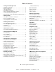
Table of Contents Vertical Termination Cap . . . . . . . . . . . . . . . . . . . . . . . . . 27 1 Listing and Code Approvals A. B. C. D. E. F. G. Appliance Certification . . . . . . . . . . . . . . . . . . . . . . . . . . . . Glass Specifications . . . . . . . . . . . . . . . . . . . . . . . . . . . . . . BTU Specifications . . . . . . . . . . . . . . . . . . . . . . . . . . . . . . . High Altitude Installations . . . . . . . . . . . . . . . . . . . . . . . . . . Non-Combustible Materials Specification. .
1 Listing and Code Approvals A. Appliance Certification MODELS: 6000GCF-IPI, 6000GCF-IPILP LABORATORY: Underwriters Laboratories, Inc. (UL) TYPE: Direct Vent Gas Fireplace Heater STANDARD: ANSI Z21.88b-2005 • CSA 2.33b-2005 This product is listed to ANSI standards for “Vented Gas Appliance Heaters” and applicable sections of “Gas Burning Heating Appliances for Manufactured Homes and Recreational Vehicles”, and “Gas Fired Appliances for Use at High Altitudes”.
Note: The following requirements reference various Massachusetts and national codes not contained in this document. G.
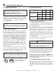
2 Getting Started A. Design and Installation Considerations C. Inspect Appliance and Components Heat & Glo direct vent gas appliances are designed to operate with all combustion air siphoned from outside of the building and all exhaust gases expelled to the outside. No additional outside air source is required. WARNING Inspect appliance and components for damage. Damaged parts may impair safe operation. • Do NOT install damaged components. • Do NOT install incomplete components.
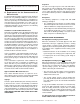
3 Framing and Clearances Note: • Illustrations reflect typical installations and are FOR DESIGN PURPOSES ONLY. • Illustrations/diagrams are not drawn to scale. • Actual installation may vary due to individual design preference. WARNING Fire Risk Provide adequate clearance: • Around air openings • To combustibles • For service access Locate appliance away from traffic areas. A.
insulation. If the appliance is being installed on a cement slab, a layer of plywood may be placed underneath to prevent conducting cold up into the room. B. Constructing the Appliance Chase A chase is a vertical boxlike structure built to enclose the gas appliance and/or its vent system. Vertical vents that run on the outside of a building may be, but are not required to be, installed inside a chase. C. Clearances Construction of the chase may vary with the type of building.
D. Mantel Projections 18 14-1/4 Note: All measurements in inches. 10-1/2 6-3/4 1 in. MIN. TOP VIEW 3 11-1/4 MANTEL LEG 3 ft. MAX. 10-1/8 9-1/2 8-3/8 Figure 3.4 Clearances to Mantel Legs or Wall Projections (Acceptable on both sides of opening.) 7-1/4 NOTE: Measurement is taken from top of the opening, NOT the top of the fireplace. Figure 3.3 Clearances to mantels or other combustibles above appliance Heat & Glo • 6000GCF-IPI, 6000GCF-IPILP • 2110-900 Rev.
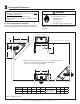
4 Termination Locations A. Vent Termination Minimum Clearances HORIZONTAL OVERHANG 2 FT. MIN. WARNING 20 INCHES MIN. VERTICAL WALL LOWEST DISCHARGE OPENING Fire Risk. Explosion Risk. Inspect external vent cap regularly. • Ensure no debris blocks cap. • Combustible materials blocking cap may ignite. • Restricted air flow affects burner operation. GAS DIRECT VENT TERMINATION CAP X 12 ROOF PITCH IS X/ 12 H (MIN.) - MINIMUM HEIGHT FROM ROOF TO LOWEST DISCHARGE OPENING WARNING Roof Pitch H (Min.) Ft.
M N P R Q (See Note 2) V T V S Electrical Service S V D* V V = VENT TERMINAL A B D* X = AIR SUPPLY INLET = 12 inches.................clearances above grade, veranda, (See Note 1) porch, deck or balcony = 12 inches.................clearances to window or door that may be opened, or to permanently closed window. (Glass) = 18 inches.................vertical clearance to unventilated soffit or to ventilated soffit located above the terminal *30 inches................
5 Vent Information and Diagrams A. Vent Table Key The abbreviations listed in this vent table key are used in the vent diagrams. First section (closest to appliance) of vertical length V2 Second section of vertical length H1 First section (closest to appliance) of horizontal length H2 Second section of horizontal length Vertical 12 V1 8-1/2 in. WARNING Fire Hazard. Explosion Risk. Asphyxiation Risk.
D. Vent Diagrams WARNING Note: The 6000 series fireplaces can adapt to SL series vent pipe, if desired. Fire Risk. Explosion Risk. Do NOT pack insulation or other combustibles between ceiling firestops. • ALWAYS maintain specified clearances around venting and firestop systems. • Install wall shield and ceiling firestops as specified. When venting off the top of the unit, use a DVP-2SL adapter and a minimum 48 inch vertical section of SL series vent pipe.
1. Top Vent - Horizontal Termination - (continued) Three Elbows V1 Minimum H1 Maximum V2 Minimum H2 Maximum V1 + V2 Minimum 6 in. 152 mm 3 ft 914 mm 1 ft 305 mm 3 ft 914 mm 1-1/2 ft 457 mm 1 ft 305 mm 3 ft 914 mm 1 ft 305 mm 3 ft 914 mm 2 ft 2 ft 610 mm 6 ft 1.8 m 2 ft 610 mm 6 ft 1.8 m 4 ft 3 ft 914 mm 9 ft 2.7 m 3 ft 914 mm 9 ft 2.7 m 6 ft H1 + H2 = 20 ft (6.1 m) Max. V1 + V2 + H1 + H2 = 50 ft (15.2 m) Max. H1 + H2 Maximum 6 ft 1.8 m 607 mm 6 ft 1.8 m 1.
2. Top Vent - Vertical Termination V1 = 50 ft. Max. (15.2 m) V1 = 3 ft. Min. (914mm) No Elbow NOTE: If installing a vertical vent/ termination off the top of the appliance, the flue restrictor should be used. See Section 7.D. V1 Figure 5.6 V1 Two Elbows H1 Maximum V2 V1 + V2 Minimum 6 in. 152 mm 3 ft 914 mm * * * 1 ft 305 mm 3 ft 914 mm * * * 2 ft 607 mm 6 ft 1.8 m * * * 4 ft 1.2 m 12 ft 3.7 m * * * V1 + V2 + H1 = 50 ft (15.2 m) Max.
2. Top Vent - Vertical Termination - (continued) V1 Three Elbows H1+ H2 V2 V1+ V2 Minimum H1+ H2 Maximum 6 in. 152 mm 3 ft 914 mm * * * 3 ft 914 mm 1 ft 305 mm 3 ft 914 mm * * * 3 ft 914 mm 2 ft 610 mm 6 ft 1.8 m * * * 6 ft 1.8 m 4 ft 1.2 m 12 ft 3.7 m * * * 12 ft 3.7 m H1 + H2 = 17 ft (5.2 m) Maximum V1 + V2 + H1 + H2 = 50 ft (15.2 m) Maximum V1 = 6 inches (152 mm) Minimum V2 H1 H2 V1 INSTALLED HORIZONTALLY Figure 5.
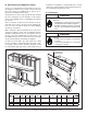
6 Vent Clearances and Framing A. Pipe Clearances to Combustibles COMBUSTIBLE SURFACE WARNING 3 IN MIN. (76 mm) Fire Risk. Explosion Risk. Maintain vent clearance to combustibles as specified. • Do not pack air space with insulation or other materials. Failure to keep insulation or other materials away from vent pipe may cause fire. HEAT SHIELD Figure 6.2 3 in. TOP CLEARANCE Fasten the shield in place using the four pilot holes provided in the part.
B. Wall Penetration Framing NOTE: Heat shields MUST overlap by a minimum of 1-1/2 in. (38 mm). The heat shield is designed to be used on a wall 4 in. to 7-1/4 in. (102 mm to 184 mm) thick. If wall thickness is less than 4 in. (102 mm) the existing heat shields must be field trimmed. If wall thickness is greater than 7-1/4 in. (184 mm) a DVP-HSM-B will be required. 12 in. 10 in. 3 IN. TOP CLEARANCE HEAT SHIELD B HEAT SHIELD A WALL SHIELD FIRESTOP WALL 1 IN. CLEARANCE BOTTOM SIDES A* 49-1/2 in.
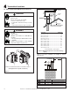
C. Vertical Penetration Framing WARNING Fire Hazard Keep loose materials or blown insulation from touching the vent pipe. • National building codes recommend using attic shield to keep loose materials/ blown insulation from contacting vent. • Hearth & Home Technologies requires the use of an attic shield. ATTIC ABOVE 10 IN. (254 MM) Installing the Ceiling Firestop • Frame an opening 10 inches by 10 inches whenever the vent system penetrates a ceiling/floor (see Figure 6.4).
7 Appliance Preparation A. Attaching Sheetrock Ledges Attach sheetrock ledges together using the attachment holes (see Figure 7.1). Attach previous assembly to the top of the unit using the provided slots. The face of the sheetrock ledge assembly and the unit surround should be flush to each other. B. Temporary Access Panel DETAIL A Once the electrical and gas lines are hooked up, the lower access panel must be put back on the unit.
C. Securing and Leveling the Appliance WARNING Fire Risk. • Prevent contact with sagging, loose insulation. • Do NOT install against combustible materials such as exposed insulation, plastic and insulation backer. The diagram shows how to properly position, level, and secure the appliance (see Figure 7.4). Nailing tabs are provided to secure the appliance to the framing members. WARNING Fire Risk. • ALWAYS maintain specified clearances around the appliance.
2. Match the amount of vertical in the system with the chart to find the appropriate position to set the Flue Restrictor (see Figure 7.7). - CHART Vertical Top Vent NG Top Vent LP 4’ 1-1 No Restrictor 8’ 2-2 1-2 15’ 3-3 3-2 20’ 3-4 3-3 25’ 3-4 3-3 30’ 4-4 3-4 35’ 4-4 3-4 40’ 5-4 4-4 45’ 5-4 4-4 50’ 5-4 4-4 E. Installing the Fiberglass Gasket The fiberglass gasket supplied in the manual bag seals between the first 8 inch (203 mm) vent component and the outer fireplace wrap.
8 Installing Vent Pipe A. Assembly of Vent Sections WARNING Do not mix pipe, fittings or joining methods from different manufacturers. • Apply a bead of silicone sealant inside the female outer pipe joint prior to joining sections. See Figure 8.1 • Only outer pipes are sealed. Do not seal the inner flue. All unit collar, pipe, slip section, elbow and cap outer flues shall be sealed in this manner, unless otherwise stated.
Note: Make sure that the seams are not aligned to prevent unintentional disconnection. This will secure the slip section to the desired length and prevent it from separating. The slip section can then be attached to the next pipe section. If the slip section is too long, the inner and outer flues of the slip section can be cut to the desired length. Cut from this end (outer) CORRECT Cut from this end (inner) Figure 8.5 Figure 8.
Securing the Vent Sections Vertical Sections Vertical sections of pipe must be supported every 8 feet after the 25 foot maximum unsupported rise. The vent support or plumber’s strap (spaced 120° apart) may be used to do this (see Figure 8.8). Horizontal Sections Horizontal sections of vent must be supported every 5 feet with a vent support or plumber’s strap. Figure 8.8 Securing Vertical Pipe Sections Figure 8.9 Securing Horizontal Pipe Sections B.
C. Installing Heat Shield and Horizontal Termination Cap WARNING Fire Hazard Impaired performance of appliance • Telescoping flue section of termination cap MUST be used when connecting pipe section to termination cap. • Maintain a 1-1/2 inch minimum overlap on telescoping flue section of termination cap. Installing the Horizontal Termination Cap Vent termination must not be recessed in the wall. Siding may be brought to the edge of the cap base.
Caulk the gap between the roof flashing and the outside diameter of the pipe. Also caulk the perimeter of flashing that contacts roof surface as shown in Figure 8.15. D. Installing Roof Flashing and Vertical Termination Cap To install roof flashing see Figure 8.13. For installation of vertical termination cap see minimum vent heights for various pitched roofs (see Figure 8.13). HORIZONTAL OVERHANG 2 FT. MIN. 20 INCHES MIN.
Assembling and Installing Storm Collar CAUTION Sharp Edges • Wear protective gloves and safety glasses during installation. Connect both halves of the storm collar with two screws (see Figure 8.16). Wrap the storm collar around the exposed pipe section and align brackets. Insert a bolt (provided) through the brackets and tighten nut to complete storm collar assembly (see Figure 8.17). Slide the assembled storm collar down the pipe section until it rests on the roof flashing. Figure 8.
9 Gas Information A. Fuel Conversions C. Gas Connection Before making gas connections ensure that appliance being installed is compatible with the available gas type. Any natural or propane gas conversions necessary to meet the appliance and locality needs must be made by a qualified technician using Hearth & Home Technologies specified and approved parts. Note: Have the gas supply line installed in accordance with local building codes, if any. If not, follow ANSI 223.1.
• Ensure that gas line does not come in contact with outer wrap of appliance. Follow local codes. • Incoming gas line should be piped into the valve compartment and connected to the 1/2 inch connection on the manual shutoff valve. WARNING Fire or Explosion Hazard • • • • Gas buildup during line purge may ignite. Purge should be performed by qualified technician. Ensure adequate ventilation. Ensure there are no ignition sources such as sparks or open flames. HIGH ALTITUDE INSTALLATIONS U.L.
10 Electrical Information A. Recommendation for Wire C. Intellifire Ignition System Wiring This appliance requires 110-120 VAC be wired to the junction box either for proper operation of the appliance. This appliance requires a 110 VAC supply to the appliance junction box for operation. A wiring diagram is shown in Figure 10.1.
INTERMITTENT PILOT IGNITOR I IGNITION MODULE 3 VAC PLUG-IN 3V TRANSFORMER S ON/OFF WALL SWITCH FLAME SPARKER/ SENSOR IGNITION MODULE (3V) WHT GROUND TO FIREPLACE CHASSIS ORG WHITE WIRE CAN BE PLUGGED INTO ANY OF #1- #5 LOCATIONS ON THE NEUTRAL SIDE TRANSFORMER 3 VAC BRN RED PIGGYBACK ON/OFF SWITCH GRN BLACK WIRE CAN BE PLUGGED INTO ANY OF #1 - #5 LOCATIONS ON THE HOT SIDE GROUND REMOTE CONTROL HOT BRN NEUTRAL BATTERY PACK LOW VOLTAGE SEE NOTE 1 BLACK ORG VALVE PLUG IN VALVE Figure 10
E. Junction Box Installation Romex Connector If the box is being wired from the appliance: • Remove the screw attaching the junction box to the outer shell, rotate the junction box inward to disengage it from the outer shell (see Figure 10.2). 14/2WG Cover Plate outside firebox • Pull the electrical wires from outside the appliance through this opening into the valve compartment.
11 Finishing A. Mantel Projections Figure 11.1 shows the minimum vertical and corresponding maximum horizontal dimensions of appliance mantels or other combustible projections above the top front edge of the appliance. FINISH WALL MATERIAL MAY BE COMBUSTIBLE - TOP AND SIDES NON-COMBUSTIBLE BOARD 0 in. 18 Note: All measurements in inches. 14-1/4 10-1/2 6-3/4 3 1 in. 1 in. 11-1/4 10-1/8 8-3/8 0 in. 0 in. SEALANT MATERIAL 9-1/2 Figure 11.
12 Appliance Setup A. Remove Shipping Materials Remove shipping materials from inside or underneath the firebox. B. Clean the Appliance 4 Clean/vacuum any sawdust that may have accumulated inside the firebox or underneath in the control cavity. 6 C. Accessories Install approved accessories per instructions included with accessories. See Service Parts List for appropriate accessories. Refer to Section 16. 7 Removing Optional GFK-160A Fan ITEM 1 - Remove front from the fireplace (see Figure 12.1).
WARNING Shock or fire risk. Use ONLY optional accessories approved for this appliance. • Using non-listed accessories voids warranty. • Using non-listed accessories may result in a safety hazard. • Only Hearth & Home Technologies approved accessories may be used safely. Figure 12.6 D. Install the Refractory E. Ember Placement WARNING Explosion Risk. • Follow ember placement instructions in manual. • Do NOT place embers directly over burner ports. • Replace ember material annually.
F. Positioning the Logs Log Assembly: LOGS-6000G If the gas logs have been factory installed they should not need to be positioned. If the logs have been packaged separately, refer to the following instructions. 1 STEP 1. CAUTION: Logs are fragile! Carefully remove the logs, grate and supporting cardboard from the inside of the fireplace See Figure 12.8. 3 4 2 5 STEP 2. Place the metal grate on top of the burner. Position the legs of the grate into the forward set of indentations in the burner top.
2 2 Figure 12.12 Front View Figure 12.13 Top View STEP 4. Log #2 (SRV2103-108): Place log #2 on top of the left side of log #1. The bottom of this log has a slot in it that goes over the tab molded into the top of log #1. The left end sits behind the simulated ember cluster on the burner top. 3 3 Figure 12.14 Front View Figure 12.15 Top View STEP 5. Log #3 (SRV2103-110): Place log #3 on top of the burner surface in front of the hump. The bottom of the log has a square groove cut through it.
G. Glass Assembly H. Screen Mesh The screen mesh is built into front. WARNING Handle glass doors with care. • Inspect the gasket to ensure it is undamaged. • Inspect the glass for cracks, chips or scratches. • Do NOT strike, slam or scratch glass. • Do NOT operate appliance with glass door removed, cracked, broken or scratched. • Replace glass door assembly as a complete appliance. I. Grilles and Trim Install optional marble and brass trim surround kits as desired.
13 Operating Instructions A. Before Lighting Appliance CAUTION If installing Intellifire ignition battery backup: • Do not install batteries if the backup mode may not be used for extended time. • Batteries may leak. • Install batteries only when needed for power outage. Before operating this appliance have a qualified technician: • Remove all shipping materials from inside and/or underneath the firebox. • Review proper placement of logs, rockwool, lava rock, and vermiculite. • Check the wiring.
B. Lighting Appliance IPI Ignition FOR YOUR SAFETY READ BEFORE LIGHTING WARNING: If you do not follow these instructions exactly, a fire or explosion may result causing property damage, personal injury or loss of life. A. This appliance is equipped with an intermittent pilot ignition (IPI) device which automatically lights the burner. Do not try to light the burner by hand. • Immediately call your gas supplier from a neighbor’s phone. Follow the gas supplier’s instructions. B.
C. After Appliance is Lit CAUTION Initial Break-in Procedure When you light the appliance, you may notice that it produces heat which does have an associated odor or smell. If you feel this odor is excessive it may require the initial three to four hour continuous burn on high followed by a second burn up to 12 hours to fully drive off any odor from paint and lubricants used in the manufacturing process. Condensation of the glass is normal.
14 Troubleshooting With proper installation, operation, and maintenance your gas appliance will provide years of trouble-free service. If you do experience a problem, this troubleshooting guide will assist a qualified service person in the diagnosis of a problem and the corrective action to be taken. This troubleshooting guide can only be used by a qualified service technician. A. Intellifire Ignition System Sympton 1. The ignitor/module makes noise, but no spark. 2.
Intellifire Ignition System - (continued) Symptom 3. (Continued) Pilot lights but continues to spark, and main burner will not ignite. (If the pilot continues to spark after the pilot flame has been lit, flame rectification has not occurred.) 4. Pilot sparks, but Pilot will not light. Possible Cause c. Module is not grounded. Verify that module is securely grounded to metal chassis of appliance. Verify that wire harness is firmly connected to module. d. Damaged pilot assembly or dirty sensor rod.
15 Maintaining and Servicing Appliance A. Maintenance Tasks Although the frequency of appliance servicing and maintenance will depend on use and the type of installation, a qualified service technician should perform an appliance checkup at the beginning of each heating season. WARNING Risk of injury or property damage. Before servicing: • Turn off gas. • Turn off electricity to appliance. • Disable remote control, if one is present. • Ensure appliance is completely cooled.
Inspect Doors, Surrounds and Fronts Maintenance Tasks 1. Assess condition of screen and replace as necessary. Recommend addition of screen if one is not present. 2. Inspect for scratches, dents or other damage and repair as necessary. 3. Verify no obstructions to airflow through the louvers. 4. Verify maintenance of proper clearance to combustible household objects. Gasket Seal, Glass Assembly and Glass 1. Inspect gasket seal and its condition. 2.
16 Reference Materials A. Appliance Dimension Diagram Dimensions are actual appliance dimensions. Use for reference only. For framing dimensions and clearances refer to Section 3.
B. Vent Components Diagrams Pipe Effective Height/Length DVP Pipe (see chart) DVP4 10-1/2 in. (267 mm) Effective Length Inches Millimeters 4 102 DVP6 6 152 DVP12 12 305 DVP24 24 610 DVP36 36 914 DVP48 48 1219 DVP6A 3 to 6 76 to 152 DVP12A 45 ° 4-7/8 in. ( 276 mm) 10-7/8 in. (276 mm) ° DVP45 (45 Elbow) 3 to 12 76 to 305 DVP12MI 3 to 12 76 to 305 DVP24MI 3 to 24 76 to 610 11-3/8 in. (289 mm) 10 in. (254 mm) 10 in. (254 mm) 1 in. (25 mm) 7-3/8 in. (187 mm) 24 in.
B. Vent Components Diagrams (continued) Note: Heat shields MUST overlap by a minimum of 1-1/2 in. (38 mm). The heat shield is designed to be used on a wall 4 in. to 7-1/4 in. (102 mm to 184 mm) thick. If wall thickness is less than 4 in. (102 mm) the existing heat shields must be field trimmed. If wall thickness is greater than 7-1/4 in. (184 mm) a DVP-HSM-B will be required. 8 in. (203 mm) Heat Shield 15-1/8 in. (384 mm) Max Effective Length 12 in.
B. Vent Components Diagrams (continued) 7-3/8 in. 1-1/2 in. 3-7/8 in. 17-3/4 in. 14 in. 10-1/2 in. DVP-TV Vertical Termination Cap Not for use on these models. 12 in. DVP-TB1 Basement Vent Cap 31 in. 13-1/4 in. 24-5/8 in. 27-1/2 in. 24-5/8 in. 13-1/4 in. RF12M Roof Flashing Multi-pak RF6M Roof Flashing Multi-pak 13-3/4 in. DVP-TRAPFL Flashing 5 in. 7-1/4 in. 12-1/2 in. 13-3/4 in. 5-1/4 in. DVP-TVHW Vertical Termination Cap (High wind) BEK Trap Cap Brick Extension 9-1/2 in. 13-7/8 in.
B. Vent Components Diagrams (continued) 8-1/8 in. (206 mm) 13 in. (330 mm) Effective Length 5-3/4 to 8-3/8 in. 146 to 213 mm 8-3/8 in. 213 mm 5-1/2 in. 140 mm 87° 3° 15 in. (381 mm) 10-1/2 in. 267 mm 10-7/8 in. 276 mm WARNING Fire Risk. • When using SL-HRC-SS and SL-HRC-ZC-SS termination caps on top vented fireplaces, a six inch minimum vertical vent section is required before installing first elbow. DVP-HRC-SS DVP-HRC-ZC-SS HORIZONTAL TERMINATION CAP Figure 16.
6000GCF-IPI C. Service Parts Beginning Manufacturing Date: May 2006 Ending Manufacturing Date: ______ Service Parts Diagram 8 6 7 9 10 12 11 Log Set Assembly 1 2 3 5 Part number list on following page. 52 Heat & Glo • 6000GCF-IPI, 6000GCF-IPILP • 2110-900 Rev.
C. Service Parts List 6000GCF-IPI IMPORTANT: THIS IS DATED INFORMATION. When requesting service or replacement parts for your appliance please provide model number and serial number. All parts listed in this manual may be ordered from an authorized dealer.
6000GCF-IPI Service Parts Beginning Manufacturing Date: May 2006 Ending Manufacturing Date: ______ Valve Assembly Parts List IPI Valve Assembly 1 12 11 2 3 5 10 4 8 9 6 7 IMPORTANT: THIS IS DATED INFORMATION. When requesting service or replacement parts for your appliance please provide model number and serial number. All parts listed in this manual may be ordered from an authorized dealer.
D. Limited Lifetime Warranty LIMITED LIFETIME WARRANTY HEAT & GLO GAS APPLIANCE PRODUCTS BASIC ONE-YEAR WARRANTY. HEAT & GLO, a brand of HEARTH & HOME TECHNOLOGIES INC., located at 20802 Kensington Boulevard, Lakeville, MN 55044, (“HEAT & GLO”) warrants to the original owner that your new HEAT & GLO Gas Appliance (the “Product”) will be free from defects in materials and workmanship for a period of one year from the date of installation.
E. Contact Information Heat & Glo, a brand of Hearth & Home Technologies Inc. 20802 Kensington Boulevard, Lakeville, MN 55044 www.heatnglo.com Please contact your Heat & Glo dealer with any questions or concerns. For the location of your nearest Heat & Glo dealer, please visit www.heatnglo.com.