H-IM-79B (12/02) December, 2002 Part Number 25001401 Replaces H-IM-79A (04/02) Installation & Operation Manual
Index Beacon II Board layout ........................................................................................................ 3 Installation Tips ................................................................................................................... 4 Brazing Power Supply Wiring .............................................................................................................................. 5 Multiple Evaporator Configuration .................................................
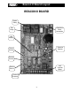
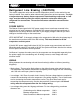
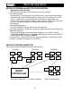
Beacon II Board Layout BEACON II BOARD Heater Relay Expansion Valve Connection Fan Relay LED Display Selection Buttons Room Sensor Defrost Sensor 24V Terminal Block Suction Sensor Suction Pressure 3
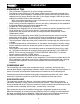
Installation Installation Tips • • • • • • • • • • • Use a minimum 18 gauge wire for all low voltage connections. The Beacon II board gets its 24 VAC power supply from a transformer mounted in the electrical end of each evaporator. On 208-240 volt systems the multi-tap transformer is shipped from our factory wired for 240 volts. If your supply voltage is 208 volt you must change to the 208 volt tap on the transformer.
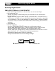
Brazing Refrigerant Line Brazing ( CAUTION ) The electric expansion valve and the suction temperature sensor on the suction line are factory installed. Care must be taken when brazing these lines at the evaporator. Too high a temperature may destroy these components. Heat absorbing compounds or “wet rags” must be used to protect the electric expansion valve when brazing the refrigerant line connections. The suction line sensor should be removed before brazing.
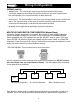
Wiring/Configuration WIRING (cont’d.) • Multiple units – The multi-in and multi-out are the communication connections. Connection sequence must follow the multi-out terminal to the multi-in terminal and the multi-out back to the multi-in terminal in a daisy chain loop. • Alarm circuit - The onboard alarm is a dry set of NC contacts which closes to indicate an alarm. The type and wiring for the alarm is customer specified.
Box Temp Control Settings BOX TEMPERATURE CONTROL SETTINGS • There is an on board room thermostat on the Beacon II board which can be adjusted to the desired room temperature. The temperature differential is 2° F. Temperature Differential When a system is in the cooling mode and the box setpoint is 35°F, the system will continue to cool until the box temperature gets to 34°F. At this point the compressor will pumpdown and shut off. The system will restart cooling when the box temperature has risen to 36°F.
Start-Up Operation Start-Up Operation SINGLE SYSTEM with 1 EVAPORATOR • Check all wiring connections to be sure they are correct and tight. • On condensing unit - Check the setting of Time Delay relay. It should be set at 1 minute (the second marker). - Check the Low Pressure switch setting on freezer units. It must be set to 0 PSIG cutout, 10 PSIG cut-in to allow positive start and operation, especially in cold ambients. This can be changed to a higher value in warmer climates.
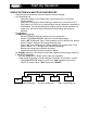
Start-Up Operation SINGLE SYSTEM with MULTIPLE EVAPORATORS • • • • • Check all wiring connections to be sure they are correct and tight. On Condensing unit - Check the setting of Time Delay relay. It should be set at 1 minute (the second marker). - Check the Low Pressure switch setting on freezer units. It must be set to 0 PSIG cutout, 10 PSIG cut-in to allow positive start and operation, especially in cold ambient. This can be changed to a higher value in warmer climates.
Start-Up Operation MULTIPLE SYSTEMS with MULTIPLE EVAPORATORS (Requires a Smart Controller) • Check all wiring connections to be sure they are correct and tight. • On condensing units - Check setting of Time Delay relay. It should be set at 1 minute (the second marker). - Check the Low Pressure Switch setting on freezer units. It must be set to 0 PSIG cutout, 10 PSIG cut-in to allow positive start and operation, especially in cold ambient. This can be changed to a higher value in warmer climates.
Start-Up Operation INITIAL POWER ON At the initial application of power to the system, the compressor and the evaporator fans will be in a 4 minute hold-off cycle and will not start immediately. When there is a call for COOLING, the expansion valve (EEV) opens, then the compressor is started. The compressor will then run for a minimum of 2 minutes in the “hold-on” cycle. (This means that the compressor will run for a minimum of 2 minutes before shutting off even if the box temperature is met.
Programming & Reviewing PROGRAMMING AND REVIEWING SETTINGS/CHANGES The Program Review button is used to program, review and change all program settings for the system. Press “PROGRAM REVIEW” button. The Setpoint item will appear on the LED. After a few seconds delay the Setpoint value will display. Each time the button is pressed a different setpoint item is displayed. Next, use the “SELECT” knob to change value of Setpoint Item.
Programming & Reviewing PROGRAMMING AND REVIEWING SETTINGS/CHANGES (cont’d.) Use the “PROGRAM REVIEW” button to select these items: • Defrost Type – “A-E ” - Selection is made for air defrost or electric defrost coil. This will automatically set the system factory defaults for air defrost and electric defrost. (See default settings.) Please note that the refrigerant type default for air defrost is R-22 and for electric defrost it is R404A. All units are shipped with factory defaults settings.
Programming & Reviewing PROGRAMMING AND REVIEWING SETTINGS/CHANGES (cont’d.) • Alarm High Temperature - “ALH” - Temperature at which a high box temperature alarm will be triggered. This does not apply during defrost. Defaults: electric defrost +5°F and air defrost +50°F. • Alarm Low Temperature - “ALL” - Temperature at which a Low Box Temperature alarm will be triggered. Defaults: Electric Defrost -15°F and Air Defrost +30°F.
Programming & Reviewing PROGRAMMING AND REVIEWING SETTINGS/CHANGES (cont’d.) Use this button to “CLEAR/TEST” Pressing this button ONCE will return the LED display to the default display. With the system in the OFF mode, pressing and holding this button will start the “TEST” mode. In the “TEST” mode it will cycle through each output for 10 seconds. The display will only show “tst” during “TEST” mode. Test mode will automatically terminate after 3 sequences.
Status Indicator LED STATUS INDICATOR LED • ERRORS E1 E2 E3 E4 E5 E6 E7 E9 • OTHERS - Room temperature sensor shorted, open or not installed - Defrost temperature sensor shorted, open or not installed - Suction temperature sensor shorted, open or not installed - Suction pressure transducer shorted, open or not installed - Outdoor temperature sensor shorted - Low superheat during cooling - Compressor shutdown (high or low refrigerant pressure or low oil pressure) - Multi-in/Multi-out wiring error Coo - R
Pumpdown / Defrost Service Mode A single pole, single throw switch (SPST) is supplied in each condensing unit for shutting off the system. Closing the “Service” switch in the condensing unit will cause the system to pumpdown and shut off. “Ser” will be displayed on the Beacon board LED and “SERVIC” is displayed on the Smart Controller LCD display. The Evaporator Fan and Heaters will be deenergized in the Service Mode.
Defrost / Alarms ELECTRIC DEFROST MODE (cont’d.) There is a 2 minute condensate drain-down period after which the compressor is started for a refreeze period. The evaporator fan stays off (fan delay). The refreeze period will last until the evaporator suction temperature is at 28°F or 2 minutes has elapsed. After this sequence, the system is back in the refrigerating mode and evaporators fans are now running.
Error Indicator ERROR INDICATOR LED At initial power up, each Beacon board checks for system errors. The system error check involves checking the various temperature sensors to determine whether any of these sensors are shorted or open.
Checking Operation of Expansion Valve CHECKING OPERATION OF EXPANSION VALVE (EEV) To check if the expansion valve is closing properly: Install a pressure gauge-set to suction line at the condensing unit. With the system running, close the valve on the liquid line, at the condensing unit. The system should pumpdown and shut off on the Low Pressure switch (LPS). If the system does not pumpdown and trip on the LPS then the compressor valves are weak and needs to be changed.
Power Failures Measuring resistance between locations A and C or B and D will always show “Open” because these locations are between the motor windings. When the valve is opening or closing, the voltage measured between A and B or C and D should be between 20 to 22 VAC. Measuring the DC volt of the EXV TEST pins, on the board, will also indicate if the expansion valve is open or close. 0 volts DC indicates the valve is closed. 5 volts DC indicates the valve is fully open.
System Defaults Table 1. Resistance/Temperature Specification Temperature °F Ohms Temperature °F 104 5,320 32 86 8,060 23 77 10,000 14 68 12,490 5 59 15,710 -4 50 19,900 -13 41 25,400 -22 Ohms 32,650 42,330 55,330 72,950 97,070 130,410 176,960 Table 2. System Defaults PARAMETERS Refrigerant Box Temperature Superheat Slave Evaporator No.
Parts List Table 3.
Expansion Valve Capacity R-22 Evaporator Temperature (°F.) +20 -20 Pressure Drop Across Valve (psi) Part Number 29320003 29320004 29320007 - 08 29320013 29320014 Valve ESVB-1 ESVB-4 ESVB-10 ESVB-15 ESVB-20 100 0.68 3.27 8.02 15.14 22.18 BTUH 8160 39240 96240 181680 266160 100 0.64 3.07 7.54 14.25 20.87 R-404A / R-507 Evaporator Temperature (°F.) +20 -20 Pressure Drop Across Valve (psi) BTUH 7680 36840 90480 171000 250440 100 0.48 2.31 5.65 10.69 15.65 BTUH 5760 27720 67800 128280 187800 100 0.42 2.
Diagnostics Beacon II Troubleshooting Guide (continued) PROBLEM Step ACTION ITEM IF NOT OK 1. Check wiring connection to the board • Correct field wiring to the board 2.
Diagnostics Beacon II Troubleshooting Guide (continued) PROBLEM E9 Step ACTION ITEM Multi-out to Multi-in Communication Wiring (only shows after initial successful connection) 1. Check for 24 volts power to the board 2. Check for crossed communication wiring (multi-out not wired to multi-in terminals) 3.
Diagnostics Beacon II Troubleshooting Guide (continued) PROBLEM Cannot get to box temperature Step ACTION ITEM IF OK IF NOT OK 1. Check system operation: Is it running? 2. 3. Check system charge Check for proper operating superheat 4. Check for high superheat and EEV wide open 5. 6. 7. 8. Check Low Pressure Safety Switch Compare equipment capacity with requirements Check box temperature setpoint Check compressor performance 9. 10. 11.
Wiring 28
Wiring 29
Wiring 30
Part No.
Part No.
Part No.
Preventive Maintenance EVAPORATORS All evaporator units should be checked once a month or more often for proper defrosting because the amount and pattern of frosting can vary greatly. It is dependent on the coil temperature, the temperature of the room, the type of product being stored, how often new product is brought into the room and the percentage of time the door to the room is open. It may be necessary to periodically change the number of defrost cycles or adjust the duration of defrost.
Service Record Date of Start-up Location Address COOLER Refrigerant Type Box Setpoint Temp. Superheat No. of Defrost/Day Defrost End Temp. CONDENSING UNIT MODEL # SERIAL # COOLER UNIT MODEL # SERIAL # FREEZER UNIT MODEL # SERIAL # R22 35°F. 8°F. 2 50°F. SYSTEM CHECKS • Check Compressor Superheat for the COOLER (Should be between 20°F. & 30°F.) YES NO • Check Compressor Superheat for the FREEZER (Should be between 20°F. & 30°F.) YES NO • Force unit into a Defrost Check heater amps.
Service Record RECORD OUTDOOR TEMPERATURE ______°F SYSTEM VOLTAGE ______Volts ______PH ______Hz Cooler Compressor Amps ______L1 ______L2 ______L3 Freezer Compressor Amps ______L1 ______L2 ______L3 Cooler Discharge Pressure ______PSIG Freezer Discharge Pressure ______PSIG Cooler Suction Pressure ______PSIG Freezer Suction Pressure ______PSIG Cooler Suction Temp. ______°F Freezer Suction Temp. ______°F Cooler Refrigerant Charge ______lbs. Freezer Refrigerant Charge ______lbs.