
Owners manual


559-734-7451 800-367-5480 FAX 559-734-7460
6400 ( R-6400 ) 12/20/06
NOTE: THIS UNIT IS DESIGNED TO MOUNT TO THE SIDE OF THE FRAME AND TO THE LEAF
SPRING ABOVE THE AXLE. DRILLING HOLES IN THE SIDE OF THE FRAME WILL BE
NECESSARY. IT WILL BE NECESSARY TO REMOVE THE TIRES, SUPPORT THE VEHICLE
BY THE AXLE WITH SAFETY STANDS AND BLOCK THE FRONT TIRES.
IMPORTANT: BEFORE BEGINNING THE INSTALLATION, CHECK TO BE SURE THERE IS ENOUGH
CLEARANCE BETWEEN THE FRAME AND THE TIRE FOR THIS ASSEMBLY. 1994
AND NEWER DODGE 4-WHEEL DRIVE PICKUPS MINIMUM CLEARNACE DISTANCE
IS (7) INCHES. SEE DIAGRAM DETAILING FENDER WELL MODIFICATIONS NECES-
SARY FOR THIS INSTALLATION. ( SEE FIG # 7 )
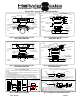
1. This unit is designed to be fully adjustable, the upper frame brackets and top air spring plate are
made up from three different brackets. Attach the air spring to the top plate with the 3/8” lock-
nuts provided. Be sure the air line fitting hole aligns with the large hole on the plate, the bent
lips on the upper plate go upwards away from the air spring. Tighten to 20 ft. lbs. max.. Install
the air line fitting into the large hole in the top of the air spring. Tighten completely so that
some of the red sealant is down inside the threaded hole. Align the hose port on the fitting to
point towards the expected air line route. Be careful not to damage the hose nut or the inner
hose sleeve when tightening the fittings. ( SEE FIG # 3 OR # 5 )
2. Attach the lower step bracket to the bottom of the air spring. Use the small bolt and lock washer
provided. A variety of slots are provided to assure proper air spring alignment. Tighten to be
snug. 20 ft lbs. max.. Reverse direction or switch holes or positions as to best fit your particular
vehicle. ( SEE FIG # 3 OR # 5 )
3. Place the assembly onto the leaf springs above the axle. The frame mount brackets are reversi-
ble above or below the top plate, however, there is a right and a left side. The left side below the
plate is the right side above the plate. Position the mount brackets to attach to the top of the up-
per air spring plate and so the frame mounting holes are against the side of the frame rail. At-
tach the frame mount brackets to the upper plate with the shortest 3/8” bolts provided. Be sure
to place the heads of the bolts on the air spring side of the bracket. Adjust the frame brackets to
compensate for any contours on your particular frame. Snug these bolts, DO NOT TIGHTEN.
( SEE FIG # 4 OR # 6 )
4. Adjust the upper brackets on the frame so the air spring is as straight up and down as possible.
Set the air spring to be between 5 and 6-1/2 inches between the brackets. The air springs come
shipped at approximately 6”, this is a good set up height. Use the (4) extra crossbars provided
as spacers to elevate one end of the step brackets on the leaf springs to make the assembly as
level as possible. ( SEE FIG # 3 )
5. With the air spring straight and at the desired setup height, use the holes in the frame brackets
and mark the locations to drill the holes, make the mark in the center of the slots to allow for
adjustment. Be sure to double check all dimensions. ( SEE FIG # 3 OR # 5 )
6. Being sure to move any lines or wires inside the frame to avoid damaging with the drill. Drill
the (4) mount holes with a 7/16” drill bit. Repeat this process for the other side.
7. Place the remaining short 3/8” bolts provided through the frame brackets and frame so the
threads are under the vehicle. Place the flat plates inside the frame on the bolts and attach with
the locknuts provided. Tighten only to be snug. Be sure not to pinch any lines, hoses or wires
inside the frame with the flat plates. ( SEE FIGURE # 4 OR # 6 )