
User Manual

TORQUE TABLE
BOLT SIZE: 3/8” = 20-30 ft. lbs. – 7/16” = 35-45 ft. lbs. – ½” = 50-70 ft. lbs. – 9/16” = 70-90 ft. lbs.
SAFETY: BEFORE STARTING YOUR INSTALLATION, BE SURE TO SET PARKING BRAKE AND CHOCK THE WHEELS.
NOTE: TO EASE INSTALLATION AND TO PROPERLY ADJUST BAR, THE WEIGHT OF THE VEHICLE MUSTBE ON THE SUSPEN-
SION, AS IF DRIVING DOWN THE ROAD. DO NOT RAISE THE VEHICLE BY FRAME.
NOTE: THIS UNIT IS DESIGNED TO REPLACE THEFACTORY INSTALLED REAR ANTI-SWAY BAR OR AS AN ADDITION IF THE
REAR ANTI-SWAY IS NOTFACTORY SUPPLIED.
NOTE: THIS KIT INCLUDES LOCK NUTS WHICH REQUIRE TIGHTENING WITH A WRENCH AFTER BEING STARTED BY HAND.
1. Remove the factory installed rear anti-sway bar (if equipped) and all factory supplied hardware. See note 7 for
removal of factory installed end link.
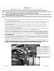
2. Locate the half round cast lugs on the differential housing at each side near the axle tubes. Install the U-bolts on
the axle between these lugs and install the saddles over the legs of the U-bolts. Orient the saddle brackets as
shown in photos (2&3).
3. Lubricate and place the D-shaped poly-bushings onto the straight areas of the bar on each side of the center
clearance hump. Place the U-plates over the bushings on the bar, position the U-plates and poly-bushings as
close as possible to the center of the hump.
4. Disconnect the emergency cable bracket located on the passenger side shock mount. Save bolt to reattach the
bracket later. Move emergency brake cable out of the way to ease sway bar installation.
5. Place the bar with the bushings and U-plates up over the top of the differential housing. Align the bushings and
U-plates so that they align with the U-bolts on the differential. Place the bar bushings and U-plates onto the U-
bolts and saddles , attach them with the flat washers and locknuts provided. Leave loose at this time to allow
for adjustment later.
6. Locate the end links and assemble with the poly bushings and 9/16” nut as in photo (4). Insert the 3/4” ID hour-
glass bushings and matching inserts in the loops of the end link that will attach to the frame rail. Insert the 5/8”
ID hourglass bushings and matching inserts in the loops of the end link that will attach to the sway bar. Lubri-
cate hourglass bushings and insert first and then insert sleeve.
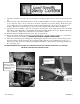
7. Installation of driver side end link will be easer if bracket in photo below is unbolted from fuel tank support.
DO NOT DISCONNECT BRAKE LINES OR ELECTRICAL CONNECTIONS, ONLY UNBOLT THE
BRACKET TO ALLOW EASIER ACCESS TO END LINK BOLT ON DRIVER SIDE.
Removal of stock end link and in-
stallation of new end link on driver
side will be easier if this bracket is
unbolted and moved away from
frame rail. Do not disconnect hoses
or electrical lines. Take care not
to damage brake line or hoses.
Replace bracket after installing end
link.
7271 ( R-7271) 04/25/2011