
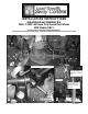
User Manual
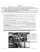

7. Attach the end links to the frame rail as shown in photos (4,5&6) using the 1/2 X 2 –1/2” bolt, washers and lock-
nut.
8. Center sway bar on the differential and move the axle mounting hardware so the bar is aligned properly. Be sure
to move any lines, wires or hoses on the axle or the inside of the frame to avoid any damage. Rotate bar up and
down to make sure there is adequate clearance to all axle and undercarriage components as the suspension ar-
ticulates. When bar is centered and proper clearances verified, tighten axle U-bolt locknuts to 60 ft-lb.
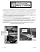
9. Attach lower end of end link to outer hole of swaybar as shown in photo six (6) using 7/16 X 2-3/4” bolt, washer
and locknut. Adjust end links so that end link bolt will clear fuel tank. Tighten 1/2” bolt to 50-60 ft-lb and 7/16”
bolt to 35-40 ft-lb. Tighten 9/16” adjustment nut on end link to 70 ft-lb.
10. Reattach emergency brake bracket and torque to factory specification.
11. Bounce the vehicle checking for clearance on all undercarriage components shocks, exhaust etc… test drive the
vehicle and recheck your installation. Recheck periodically on a regular basis thereafter.
12. The sway bar arms have three mounting holes. Mounting the sway bar on the outer hole is the nominal position.
For firmer settings, use the inner holes. We recommend starting with the outer mounting hole as in photo ( 2 )
until you are accustomed to the vehicles new handling characteristics. Then select the mounting point that best
fits your driving style
ATTENTION INSTALLER: BE SURE THE CUSTOMER RECEIVES THIS INSTRUCTION SHEET, ALL WARNING
AND NOTE CARDS AND THE WARRANTY FORM.
3/4” ID Houglass
Bushings on frame
end. Attach with 1/2”
Hardware and torque
to 50-60 ft-lb.
Attach end link to
end hole for initial
adjustment.
5
6
7271 ( R-7271) 04/25/2011