
Humidifier User Manual
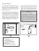

Wiring
All field wiring should be routed up through the knockout
in the bottom panel or in the back of the unit.
Supply Power.
1. Insure that minimum circuit ampacity is 15 amps.
2. Terminals are provided in the electrical compartment
for field connection of the main power supply legs
(single phase) and a ground wire.
3. Install external overcurrent protection and provide
wiring in accordance with the NEC, state and local
codes.
4. Power supply must be “clean”: free of spikes, surges
and sags: +10%, -15% of nominal.
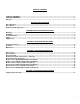
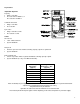
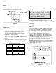
Electrical Characteristics
Capacity Steam Output
Lbs. / hr 4 8
Kg / hr 1.8 3.7
Input kW
1.33 2.66
Volts/Ph: Amps
120/1 11.8 N/A
230/1 5.9 11.8
Control Circuit Connections
WARNING!
Do Not install any controls inside the
Herrmidifier 6000 cabinet. Installations of an
y
extraneous devices inside the electrical
compartment rnay cause erratic behavior of the
circuitry and will VOID the warranty.
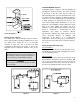
6000-1,2
The 6000 units with built-in blowers require no external
control wiring since the humidistat and air proving switch
are built-in.
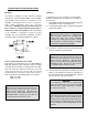
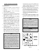
6000-3,4
The control wiring for the ducted version is to be
connected to the 5 pole controls terminal strip located in
the low voltage compartment. Terminals #1 and #2 are
for connecting the control and high limit humidistats as
well as the air proving switch in series (all included). If
desired, terminals #3 and #4 are relay contacts to
energize your fan relay (Relay contact rating 12 Amps at
125 VAC, 8 Amps at 250 VAC). With this optional wiring,
on a call for humidity, the humidifier will close the
interlock relay and energize the fan blower. The air-
proving switch must not be used if the fan interlock
is utilized. All control wiring should be 22 AWG or larger
(See figure 8). Consult with the factory if you have any
special wiring requirements.
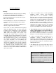
Figure 7
Figure 8
9