
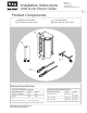
User guide


2
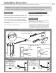
Installation Directions
4. Prepare frame using appropriate template for your lockset
and faceplate combination (see page 3).
1. Select the appropriate Plug In Connector that matches system
power and electrically connect as illustrated in Diagram 2. For
12V DC, the pigtail marked “12 VDC” should be used. For 24V DC,
the pigtail marked “24 VDC” should be used. If no connector is
present, congure the wires as illustrated within Diagram 2.
2. If your strike is supplied with the LATCHBOLT MONITOR (LBM),
or LATCHBOLT STRIKE MONITOR (LBSM), see Diagrams 3 & 4 for
wiring instructions.
3. For available faceplate options, see page 4.
Prepare Strike
Prepare Frame
LBSM WIRING
White
Orange
Closed When
Green Open When
Common
LBM WIRING
Brown
Blue
Open When Locked
Yellow Closed When Locked
Common
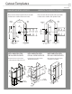
Cutout Templates
1006 WITH CYLINDRICAL LOCKSETS
2X 12-24
UNC THREADS
2X 12-24
UNC THREADS
1-11/16"
1-1/4"
1-11/16"
1-1/4"
5/32”
1-11/16"
9"
1-3/8"
METAL JAMB INSTALLATION
FOR 1006 SERIES FACEPLATES
Cutout dimenstions for option faceplates:
J, K, KM, N, NM, A, AM, H, HM, HT, T, Z, R and E
METAL JAMB INSTALLATION
FOR 1006 -D SERIES FACEPLATES
Cutout dimenstions for option faceplates:
KD, ND, AD, HD, HTD and TD
WOOD JAMB INSTALLATION
FOR 1006-2 SERIES FACEPLATES
Cutout dimenstions for option faceplates:
J2, K2, KM2, N2, T2, H2 AND A2
1006 WITH MORTISE LOCKSETS
Inches [mm]
4-7/8"
[123.83]
4-1/8"
[104.77]
[85.72]
3-3/8"
[42.86]
[31.8]
[42.86]
[85.72]
3-3/8"
[31.8]
4-1/8"
[104.77]
4-7/8"
[123.83]
[85.72]
3-3/8"
[42.86]
[34.92]
[228.6]
3
C
L
C
L
29/32”
[23.01]
19/32”
[15.08]
C
L
Strike
Prep
3/8"
4"
8"
1-1/4"
1-3/4"
Vertical
Centerline
C
L
Lock
4-7/8"
4-1/8"
3-1/2"
5/8"
1-1/4"
Mortise
Lockset
C
L
Strike
C
L
Strike
Prep
5/8"
1-1/4"
Cylindrical
Lock
C
L
C
L
STRIKE
LOCK
Vertical
Centerline
2-1/4"
1-1/4"
1-3/4"
Please note the horizontal centerline of the electric strike
in relation to the centerline of the mortise lockset.
Please note the horizontal centerline of the electric strike
in relation to the centerline of the cylindrical lockset.
[203.2]
[101.6]
[44.45]
[31.8]
[9.53]
[15.88]
[31.8]
[88.9] [104.77]
[123.83]
[57.15]
[31.8]
[44.45]
[15.88]
[31.8]
3-1/2"
[88.9]
4-1/8"
[104.77]
4-7/8"
[123.83]
DIAGRAM 2: 12V or 24V SELECTOR
Brown
Blue
Yellow
White
Orange
Green
DIAGRAM 3: LATCHBOLT MONITOR DIAGRAM 4: LATCHBOLT STRIKE MONITOR
BLACK
RED/GREEN
RED
VIOLET
VIOLET
BLACK
RED/GREEN
IF CONNECTOR IS MISSING
(+ 12 VDC)
(-NEG)
(+ 24 VDC)
(-NEG)
ELECTRIC
STRIKE
ELECTRIC
STRIKE
CONNECT
TOGETHER
CONNECT
TOGETHER
CONNECT
TOGETHER
Finish Installing
5. Attach the electric strike to the jamb using the screws
provided with the faceplate option kit.
RED
Latch Present
Latch Present
Make sure you check polarity
prior to connecting the wires.
Violet
(+24 VDC)
Black
(-NEG)
Red
(+12 VDC)
Black
(-NEG)
Note: The electric strike solenoid is polarized and will
only operate if the current ow from the power source
is provided in the correct direction. Identify positive
(+) and negative (-) wires from the power source and
connect to one of the pigtails as shown in Diagram 2.
CAUTION! Before connecting any device at the installation site, verify input voltage and polarity of service wiring with
a multimeter. Many power supplies and low voltage transformers operate at higher levels than listed. Any input voltage
exceeding10% of the solenoid rating may cause severe damage to the unit and will void the warranty.