
Owner manual


2
Installation Directions
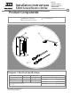
CAUTION! Before connecting any device at the installation site, verify input voltage using a multimeter.
Many power supplies and low voltage transformers operate at higher levels than listed. Any input voltage exceeding
10% of the solenoid rating may cause severe damage to the unit and will void the warranty.
Brown
Blue
Yellow
DIAGRAM 2: 12V to 24V CONVERSION
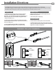
4. Prepare frame using appropriate template for your
faceplate (see pages 3-6).
5. Attach faceplate to strike body
1. Select the appropriate Plug In Connector that matches
system power and electrically connect as illustrated in
Diagram 2. For 12V AC/DC or 16V AC, the pigtail marked “12
VDC” should be used. For 24V AC/DC, the pigtail marked
“24 VDC” should be used.
2. Verify that the strike is in the correct mode of operation.
This unit ships in Fail Secure mode. If you need to convert to
fail safe see Diagram 5.
3. If using Latchbolt Monitor (LBM) or Latchbolt Strike
Monitor (LBSM) see Diagram 3 & 4 to complete wiring.
Prepare Strike
6. Connect wires from the power source to the strike.
7. Install the electric strike unit in jamb cutout using the
screws provided with the faceplate option kit. If horizontal
adjustment is needed, see Diagram 6.
Finish Installing
Prepare Frame
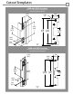
LBM WIRING
White
Orange Normally Open
Green
Normally Closed
Common
Blue
Yellow
LBSM WIRING
Brown
Normally Open
Normally Closed
Common
White
Orange
Green
DIAGRAM 3: LATCHBOLT MONITOR DIAGRAM 4: STRIKE MONITOR
RED
RED/GREEN
BLACK
VIOLET
RED
BLACK
VIOLET
RED/GREEN
IF CONNECTOR IS MISSING
(+ 12 VDC)
(-NEG)
(+ 24 VDC)
(-NEG)
ELECTRIC
STRIKE
ELECTRIC
STRIKE
CONNECT
TOGETHER
CONNECT
TOGETHER
CONNECT
TOGETHER