INDOOR PRESERVATION Refrigerators, Freezers and Wine Storage KRP / KRB / KRC / KFC / KWC / KRW Installation Manual
EN IF THE INFORMATION IN THIS MANUAL IS NOT FOLLOWED EXACTLY, A FIRE OR EXPLOSION MAY RESULT CAUSING PROPERTY DAMAGE, PERSONAL INJURY, OR DEATH. Do not store or use gasoline or other flammable vapors and liquids in the vicinity of this or any other appliance. Installation and service must be performed by a qualified installer or service agency. DO NOT REPAIR, REPLACE OR REMOVE ANY PART OF THE APPLIANCE UNLESS SPECIFICALLY RECOMMENDED IN THE MANUAL.
TABLE OF CONTENTS 1 2 3 3 4 4 12 15 27 36 38 SAFETY PRECAUTIONS - BEFORE YOU BEGIN MODEL NUMBERS RATING LABEL REGULATORY / CODE REQUIREMENTS IMPORTANT CHILD SAFETY LOCATION AND PREPARATION CONNECTIONS OVERLAY PANELS FINAL INSTALLATION TESTING AND INITIAL START UP PARTS AND SERVICE EN SAFETY PRECAUTIONS - BEFORE YOU BEGIN When properly cared for, your Hestan appliance will provide safe, reliable service for many years. When using this appliance, basic safety practices must be followed as outlined below.
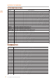
MODEL NUMBERS REFRIGERATION MODELS Model EN KRPR36 KRPL36 KRPR36-XX KRPL36-XX KRBR36 KRBL36 KRBR36-OV KRBL36-OV KRBR36-XX KRBL36-XX KRCR24 KRCL24 KRCR24-OV KRCL24-OV KRCR24-XX KRCL24-XX KRCR30 KRCL30 KRCR30-OV KRCL30-OV KRCR30-XX KRCL30-XX Description Bottom Mount Refrigerator, Top Compressor, Pro, Right Hinged, 36" Bottom Mount Refrigerator, Top Compressor, Pro, Left Hinged, 36" Bottom Mount Refrigerator, Top Compressor, Pro, Color, Right Hinged, 36" Bottom Mount Refrigerator, Top Compressor, Pro, Colo
MODEL NUMBERS (CONT.) WINE MODELS Model No.
IMPORTANT CHILD SAFETY Risk of child entrapment. Before you throw away your old refrigerator or freezer: EN • Take off the doors • Leave the shelves in place so that children may not easily climb inside. LOCATION AND PREPARATION PREPARATION AND UNPACKING Before moving the refrigerator: • • • Protect any finished flooring to prevent damage. The grille and trim pieces are packaged on the back of the unit. Handles and other items may also be packaged on the back.
LOCATION AND PREPARATION (CONT.
LOCATION AND PREPARATION (CONT.
LOCATION AND PREPARATION (CONT.
LOCATION AND PREPARATION (CONT.
LOCATION AND PREPARATION (CONT.
LOCATION AND PREPARATION (CONT.) PREPARING THE INSTALLATION Transport to installation site and unpacking EN Since this is a large and heavy appliance, before transporting the appliance, check the access to the location where it will be installed (door size, maneuvering space in stairwells, etc.). The side trim, door handles (non OV models), grill, and possibly other items will be packaged on the back of the appliance.
LOCATION AND PREPARATION (CONT.) Additional included items Several items are shipped inside the appliance. These include: • • • • • EN Manuals Wood panels installation hardware (-OV models) Water connection fitting, water filter (models with ice maker) Anti-tip brackets Care items - polishing cloth and/or sponge.
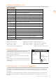
LOCATION AND PREPARATION (CONT.) CUT-OUT DIMENSIONS AND INSTALLATION METHODS - NON-FLUSH If installing non-flush, the same side trim is used and the same cutout width is required. EN 36: 35-1/2” [900] 30: 29-5/8” [750] 24: 23-3/4” [600] 18: 17-3/4” [451] A 1/4” [6,5] 3/8” [10] A A A: Lateral / side connection kit (SEE NOTE ON PG. 27) CONNECTIONS ELECTRICAL AND WATER CONNECTION Do not use extension cords and/or multiple adapters for the power supply connection.
CONNECTIONS (CONT.) The appliances are delivered from the factory for operation at 110V-120V AC - 60Hz (US and Canada). They are provided with a suitable supply cord and plug to be connected to an appropriate 15A socket (US and Canada) provided with an effective grounding. EN A circuit breaker should also be installed and should be easily accessible so that it can be easily switched off before performing any installation or maintenance.
CONNECTIONS (CONT.) KRP MODELS Connect as follows: EN Unwind the electric cord and connect it directly to the wall socket. Observe the information display. If the appliance is not in Stand-by condition or if any lights are on, press the On/Off button for three seconds to switch it off. Back of appliance Electrical connection Water connection Connect the water line to the threaded connection at the base of the unit.
OVERLAY PANELS DOOR AND DRAWER OVERLAY PANEL PREPARATION Decorative panels: The dimensions of the panels are indicated in the table and drawings on following pages. EN 1 To align panels with other kitchen structures, sizes can be adjusted if the door panel needs to be higher than the upper edge of the refrigerator door, and/or the drawer panel needs to lower than the edge of the drawer.
OVERLAY PANELS (CONT.) DOOR AND DRAWER OVERLAY PANEL PREPARATION (continued) Mounting the Brackets EN 4) Position the brackets on each set of marks to make sure they are aligned. (4) Note that the support bracket mounts with its flange toward the top of the door. • If necessary, drill starter holes in the panel. (5) (Use a drill stop to avoid drilling through or damaging the finish surface.) The installation kit includes 5/8” screws.
OVERLAY PANELS (CONT.) PANEL DIMENSIONS KRB - OV EN KRBx36-OV Hinge Right A 35-1/4” [897 ] 35-1/4” [897] B 14” [355.5] C 10-1/4” [261] 14” [355.5] D 16-1/2” [418 ] 15-1/4” [386] E 16-1/2” [418] 15-1/4” [386] 14” [354.5] A B C ½” [13] min 54-3/4” [1390] 6-¼” [157] D E D E max 25” [635] 4” [100] 26” [660] 15- ⁄8” [382] 45-¾” [1163] 1- 3⁄8” [34] 1-3⁄8 ” [34] 1 14” [354.5] 20” [507.
OVERLAY PANELS (CONT.) PANEL DIMENSIONS KRW - OV EN < 7- 7⁄8” 42-3⁄8” [1075] [200] 12-7⁄8” [327] 5- 3⁄8” [135] 5-3⁄8” [135] 4-½”[115] A ¼” [6.5 ] ¼” [6.5 ] 23-½” [597] 23-½” [597] D 10-7⁄8” [276.5] 9-3⁄8” [236.5] E 9 3⁄8” [236.5] 10-7⁄8” [276.5] 8” [203.5] 8” [203.5] H 10-5⁄8” [270.5] 9-1⁄8” [230.5] I 9-1⁄8” [230.5] 10-5⁄8” [270.5] F/G min 54-¾” [1390] 5- 7⁄8” [148.
OVERLAY PANELS (CONT.) PANEL DIMENSIONS KRC - OV, KFC - OV See "PANEL DIMENSIONS KRW - OV" on page 18 for KRW models. See "PANEL DIMENSIONS KWC - OV" on page 20 for KWC models. 30” -OV Column Models Hinge Left EN 24”-OV Column Models 18”-OV Column Models Hinge Right Hinge Left Hinge Right Hinge Left Hinge Right A 29-3⁄ 8” [747] 29-3⁄ 8” [747] 23-1⁄ 2” [597] 23-1⁄ 2” [597] 17-5⁄8” [447] 17-5⁄8” [447] B B 13-1⁄ 2” [343] 13-1⁄ 2” [343] 10-7⁄ 8” [276.
OVERLAY PANELS (CONT.) PANEL DIMENSIONS KWC - OV EN MODEL KWCx24-OV MODEL KWCx18-OV Left Hinge Right Hinge 23-1⁄2” [597] 17-5⁄8” [447] 17-5⁄8” [447] 10-7⁄ 8” [276.5] 10-1⁄ 2” [268] 7-7⁄8” [200] 7-7⁄8” [200] 10-1⁄ 2” [268] 10-7⁄ 8” [276.
OVERLAY PANELS (CONT.) PANEL DIMENSIONS KRB 36-OV AND KRW 24-OV Panels can have thickness ranging between 3/4” [18 mm] and 1-1/8“ [28 mm]. EN Door panels can have a maximum weight 51 lbs [23 kg] and drawer panels may be a maximum weight of 25 lbs [11 kg]. Exceeding these weights could void your warranty for any service issues which can be attributed to overweight panels. The hinge mechanism on Hestan refrigerators is considered to be `Zero-clearance`.
OVERLAY PANELS (CONT.) PANEL DIMENSIONS KFC - OV, KRC - OV AND KWC - OV Panels can have thickness ranging between 3/4” [18 mm] and 1-1/8“ [28 mm]. EN Door panels can have a maximum weight 51 lbs [23 kg] and drawer panels may be a maximum weight of 25 lbs [11 kg]. Exceeding these weights could void your warranty for any service issues which can be attributed to overweight panels. The hinge mechanism on Hestan refrigerators is considered to be `Zero-clearance`.
OVERLAY PANELS (CONT.) MOUNTING HANDLES ON OVERLAY PANELS Handles must be mounted on the panels before the panels are applied to the fridge. EN 1 Place the handle on top of the holes and insert the screws through the panel and into the handle support. 2 Handles not provided with Overlay (-OV) Models (sample handle shown) Accurately measure the distance between hole centers for correct dimensions to apply before drilling the mounting holes in your panels.
OVERLAY PANELS (CONT.) PREPARING DOOR AND DRAWER FOR OVERLAY PANELS The adjusting screws and hanger bolts must be threaded into place in the door (and drawer, if applicable) before applying the decorative panels. EN Install the vertical adjustment screws into the bottom of the drawer (if applicable) 2-3 turns deep. The vertical adjustment screws for the door panel are installed after applying the door panel. Install one hanger bolt into each recess - only 2-3 turns deep.
OVERLAY PANELS (CONT.) MOUNTING OVERLAY PANELS TO DRAWER EN Once all brackets and small brackets have been applied to the panels, you can begin installing the bottom drawer panel. 1 2 1 Leave the vertical adjustment screws just a few turns in. 2 Mount the bottom drawer panel: Make sure the height adjustment screw heads are under the adjusting brackets. Then fit the attachment brackets over the hanger bolts. Final adjustment must be done after the appliance is in place and the side trim mounted.
OVERLAY PANELS (CONT.) MOUNTING OVERLAY PANELS TO DOOR EN Hook the panel to the hanger bolts starting from the top aligning brackets (6). After the panel is hooked on all hanger bolts, install the two vertical adjustment screws. See (9) below. 6 7 At this point, alignment between the panel and adjacent cabinets can be adjusted using the alignment brackets and brackets (7) and (8). 8 9 Vertical alignment: tighten or loosen the screws in the brackets to raise or lower the panel.
FINAL INSTALLATION INSTALLING TWO OR MORE UNITS TOGETHER - TOTAL OPENING WIDTH The best practice for planning and installing built-in units together is to combine the actual widths of each unit, and add another 1/8" [3 mm] to get the total opening width. When placed next to each other, the side profile trims are used to hold the units together (discussed on the next page).
FINAL INSTALLATION (CONT.) INSTALLING TWO OR MORE UNITS TOGETHER - CONNECTIONS Installing two or more units as built-ins next to each other requires a Central Connection Kit. EN (Not included - must be ordered as a separate accessory) AKRCJK (for KRB, KRC, KFC, KWC and KRW Models in Stainless Steel or color) AKRCJK-OV (for KRB, KRC, KFC, KWC and KRW overlay models ) AKRCJKP (for KRP Models) The appliance comes with side connectors on each side.
FINAL INSTALLATION (CONT.) INSTALLING TWO OR MORE UNITS TOGETHER (cont.) Position the two units so that, when joined, they can be rolled into their final position. EN 1) For KRP units, place the anti-condensation insulator according to its directions. 1 2) Place the units side by side, and check leveling. The two units must be at the same height before connecting. (Item 3, this page) The side connectors should just touch along their length.
FINAL INSTALLATION (CONT.) MOVING SINGLE UNIT INTO POSITION Side connectors with decorative trim pieces are provided to secure the appliance to adjacent cabinetry. EN Make sure the side connectors will fit the cutout width. See "CHECK/ADJUST SIDE TRIM" on page 31. All but KRP: The unit does not need a ventilation shaft in the cabinet for cooling. KRP: See "INSTALLATION CUT-OUT - KRP MODELS" on page 5 for ventilation requirements.
FINAL INSTALLATION (CONT.) LEVELING THE APPLIANCE Adjust the appliance level by means of the front leveling feet and the rear adjustable wheels. EN Leveling must be done after the appliance has been moved into place. Level as follows: 1) Remove the bottom grille if necessary (it is kept in position by magnets) 2) Adjust the front using the leveling feet (1) by means of a 17 mm (or 11/16") open-end or adjustable wrench.
FINAL INSTALLATION (CONT.) ANTI-TIP SAFETY 5] 8” [4 EN To avoid danger of the appliance tipping over it is mandatory to secure the appliance to the wall by means of the two provided brackets. 2-3⁄8” [59] 1-5⁄ 6” [1 52] MOUNTING SAFETY ANTI-TIP BRACKETS - All except KRP series When using the anti-tip brackets, they should be applied as illustrated using the provided screws and wall anchors. 1) Find the mounting holes on top of the appliance, and determine how the bracket must align with the wall.
FINAL INSTALLATION (CONT.) MOUNTING SAFETY ANTI-TIP BRACKETS - KRP series To avoid danger of the appliance tipping over it is mandatory to secure the appliance to the wall by means of the two provided brackets. 1) The appliance has one screw in place where each bracket will attach. (See figure to right.) Remove the screws and set aside. EN 1 Anti-tip mounting screws 2) Determine location of brackets and mark the wall accordingly. Note that the brackets can be installed facing in or out, as preferred.
FINAL INSTALLATION (CONT.) MOUNTING THE HANDLES AND ENDCAPS Handles and endcaps are provided with all stainless and color models. Handles are located in protective wrapping, taped to the back of the refrigerator. Remove the handles before moving the refrigerator into its cut-out or opening. Endcaps are located in a cardboard box inside the refrigerator. EN It is recommended that two people work together to assemble and apply the handles and endcaps. Follow the steps below to complete the mounting process.
FINAL INSTALLATION (CONT.) PROPER AIR CIRCULATION (Except KRP) A forced air system assures ventilation through a grille positioned in the lower front of the unit. If the kitchen design includes an applied toekick, it must have ample openings/slots to maintain proper airflow as illustrated below. Holes/slots can be of any size and shape, provided that the total open area amounts to 50% of the overall size of the decorative cover.
FINAL INSTALLATION (CONT.) PROPER AIR CIRCULATION (KRP) EN For KRP models, ventilation is provided by a forced air system through a grille in the top of the refrigerator. This open space in the grille must not be restricted by any cover or device that would reduce the proper airflow, as it would reduce product efficiency and increase energy consumption. A vent must be provided at the rear for the air to exit. See page 5 for location and dimensions.
TESTING AND INITIAL START-UP (CONT.) INITIAL STARTUP Once the appliance is plugged in, the display will show the Hestan logo, a brief info screen, then go dark. EN Turn the appliance ON by pressing the Power button for three seconds. The display will show a Hestan logo, then the message “Initial test, please wait...” for 2-3 minutes. After this phase the compressors will start up and remain on until the default temperature (set at the factory) is reached.
TESTING AND INITIAL START-UP (CONT.) Bottom Drawer Models KRP, KRB, and KRW have a bottom drawer which defaults to freezer operation. The drawer can also be set to other modes of operation. See the Use and Care manual for more information. EN Readiness If at first the Start Up message does not appear but other information in the display does appear (such as Fridge too warm, Freezer too warm, or audible signals are heard), the refrigerator has still begun the normal cooling process.
LE NON-RESPECT À LA LETTRE DE CES INSTRUCTIONS PEUT CAUSER UN INCENDIE OU UNE EXPLOSION, QUI POURRAIT ENTRAÎNER DES DOMMAGES MATÉRIELS, DES BLESSURES OU LA MORT. Ne pas entreposer ou utiliser d’essence ou tout autre liquide ou gaz inflammable à proximité de cet appareil ou de tout autre appareil. L’installation et le service doivent être effectués par un installateur qualifié ou une agence de service.
TABLES DES MATIERES 1 2 3 3 4 4 12 15 27 36 38 FR PRÉCAUTIONS DE SÉCURITÉ - AVANT DE COMMENCER NUMÉROS DE MODÈLE PLAQUE SIGNALÉTIQUE EXIGENCES RÉGLEMENTAIRES / CODE POUR LA SÉCURITÉ DES ENFANTS EMPLACEMENT ET PRÉPARATION CONNEXIONS PRÉPARATION DES PANNEAUX DÉCORATIFS INSTALLATION FINALE ESSAIS ET DÉMARRAGE INITIAL LISTE DES PIÈCES / SERVICE PRÉCAUTIONS DE SÉCURITÉ - AVANT DE COMMENCER S’il est bien entretenu, cet appariel Hestan procurera un service sûr et fiable pendant de nombreuses années.
NUMÉROS DE MODÈLE MODÈLES DE RÉFRIGÉRATION Modèles KRPR36 KRPL36 KRPR36-XX KRPL36-XX KRBR36 KRBL36 KRBR36-OV KRBL36-OV KRBR36-XX KRBL36-XX KRCR24 KRCL24 KRCR24-OV KRCL24-OV KRCR24-XX KRCL24-XX KRCR30 KRCL30 KRCR30-OV KRCL30-OV KRCR30-XX KRCL30-XX Description FR Réfrigérateur à congélateur inférieur, compresseur supérieur, Pro, charnière à droite, 36 po Réfrigérateur à congélateur inférieur , compresseur supérieur, Pro, charnière à gauche, 36 po Réfrigérateur à congélateur inférieur, compresseur supérieur
NUMÉROS DE MODÈLE (SUITE) MODÈLES DE VIN Modèles FR KWCR18 KWCL18 KWCR18-OV KWCL18-OV KWCR18-XX KWCL18-XX KWCR24 KWCL24 KWCR24-OV KWCL24-OV KWCR24-XX KWCL24-XX KRWR24 KRWL24 KRWR24-OV KRWL24-OV KRWR24-XX KRWL24-XX Description Colonne de vin, charnière à droite, 18 po Colonne de vin, charnière à gauche, 18 po Colonne de vin, recouvrement, charnière à droite, 18 po Colonne de vin, recouvrement, charnière à gauche, 18 po Colonne de vin, couleur, charnière à droite, 18 po Colonne de vin, couleur, charnière à
POUR LA SÉCURITÉ DES ENFANTS FR Risque d’enfermement pour les enfants. Avant de jeter un vieux réfrigérateur ou congélateur: • Retirer les portes • Laisser les étagères en place afin d’empêcher que des enfants grimpent dedans. EMPLACEMENT ET PRÉPARATION PRÉPARATION ET DÉBALLAGE Avant de déplacer le réfrigérateur: • Protégez tout revêtement de sol fini pour éviter tout dommage. • La grille et les éléments de garniture sont emballés à l'arrière de l'unité.
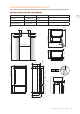
EMPLACEMENT ET PRÉPARATION (SUITE) DÉCOUPE D’INSTALLATION - MODÈLES KRP FR Hauteur de l’encastrement Encombrement avec porte ouverte Largeur Profondeur (sans panneau) Largeur de 35-1/2 po [900 mm] l’encastrement Angle d’ouverture 57 po [1448 mm] 105° de la porte 35-3/8 po [899 mm] Hauteur 83-1/2 po [2120 mm] + 1 po [25 mm] 84 po [2134 mm] 25 po [635 mm] Espace à réserver aux supports anti-renversement 9 po [230] 4 po [100] min 3⁄8 po [10] 25 po [635] 50 po [1296] min 3⁄8 po [10] 20-3⁄8 po [516] 3-
EMPLACEMENT ET PRÉPARATION (SUITE) DÉCOUPE D’INSTALLATION - MODÈLES KRB AVEC SS OU COULEUR Hauteur de l’encastrement Encombrement avec porte ouverte Largeur Profondeur Largeur de 35-1/2 po [900 mm] l’encastrement Angle d’ouverture 57 po [1448 mm] 105° de la porte 35-3/8 po [899 mm] Hauteur 83-1/2 po [2120 mm] + 1 po [25 mm] 25 po [635 mm] 84 po [2134 mm] Espace à réserver aux supports anti-renversement 57 po [1448] 40 po [1016] 4 po [100] 9 po [230] 5-½ po [140] min 84 po [2134] 35-½ po [900] 5° 3
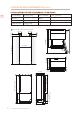
EMPLACEMENT ET PRÉPARATION (SUITE) DÉCOUPE D’INSTALLATION - MODÈLES KRB-OV (RECOUVREMENT) Hauteur de l’encastrement Encombrement avec porte ouverte Largeur Profondeur (sans panneau) FR Largeur de 35-1/2 po [900 mm] l’encastrement Angle d’ouverture 57 po [1448 mm] 105° de la porte 35-3/8 po [899 mm] Hauteur 83-1/2 po [2120 mm] + 1 po [25 mm] 84 po [2134 mm] 24 po [610 mm] Espace à réserver aux supports anti-renversement 3⁄8 po [10] 24 po [610] 22 po [560] min 84 po [2134] 35-½ po [900] 38-27⁄32 po [
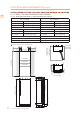
EMPLACEMENT ET PRÉPARATION (SUITE) DÉCOUPE D’INSTALLATION - MODÈLES KRC, KFC, KWC, KRW AVEC SS OU COULEUR FR RÉFRIGÉRATEURS ET CONGÉLATEURS À COLONNE DE 18, 24 ET 30 PO COLONNE À VIN DE 18, 24 PO ET RÉFRIGÉRATEUR DE 24 PO AVEC VIN Hauteur de l’encastrement Largeur de l’encastrement Modèles de 18 po 84 po [2134 mm] Modèles de 18 po 17-3/4 po [451 mm] Modèles de 24 po 84 po [2134 mm] Modèles de 24 po 23-3/4 po [600 mm] Modèles de 30 po 84 po [2134 mm] Modèles de 30 po 29-5/8 po [750 mm] Encombrement avec por
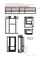
EMPLACEMENT ET PRÉPARATION (SUITE) DÉCOUPE D’INSTALLATION - MODÈLES KRC, KFC, KWC, KRW-OV KRW-OV (RECOUVREMENT) RÉFRIGÉRATEURS ET CONGÉLATEURS À COLONNE DE 18, 24 ET 30 PO COLONNE À VIN DE 18, 24 PO ET RÉFRIGÉRATEUR DE 24 PO AVEC VIN Hauteur de l’encastrement Largeur de l’encastrement Modèles de 18 po 84 po [2134 mm] Modèles de 18 po 17-3/4 po [451 mm] Modèles de 24 po 84 po [2134 mm] Modèles de 24 po 23-3/4 po [600 mm] Modèles de 30 po 84 po [2134 mm] Modèles de 30 po 29-5/8 po [750 mm] Encombrement avec p
EMPLACEMENT ET PRÉPARATION (SUITE) PRÉPARATION DE L’INSTALLATION Transport vers le site d’installation et déballage FR S’agissant d’un appareil lourd et volumineux, vérifiez, avant de le transporter, l’accès à l’emplacement où il sera installé (taille de la porte, espace de manœuvre dans la cage d’escalier, etc.). La garniture latérale, les poignées de porte (modèles non OV), le gril et éventuellement d’autres articles seront emballés à l’arrière de l’appareil.
EMPLACEMENT ET PRÉPARATION (SUITE) Articles inclus supplémentaires Plusieurs articles sont expédiés à l’intérieur de l’appareil. Ceux-ci inclus: FR • Manuels • Matériel d’installation des panneaux (modèles -OV) • Raccord de connexion à l’eau, filtre à eau (modèles avec machine à glaçons) • Supports anti-renversement • Articles de soin - chiffon et / ou éponge à lustrer.
EMPLACEMENT ET PRÉPARATION (SUITE) DIMENSIONS DE LA DÉCOUPE ET MÉTHODES D’INSTALLATION - NON ENCASTRÉ FR En cas d’installation non encastré, la même garniture latérale est utilisée et la même largeur de découpe est requise. 36: 35-1/2 po [900] 30: 29-5/8 po [750] 24: 23-3/4 po [600] 18: 17-3/4 po [451] A 1/4 po [6,5] 3/8 po [10] A A A: Kit de connexion latérale (VOIR LA NOTE SUR PG.
CONNEXIONS (SUITE) Les appareils sont livrés de l'usine pour fonctionner à 110V-120V AC - 60Hz (États-Unis et Canada). Ils sont fournis avec un cordon d'alimentation et une fiche appropriés à brancher sur une prise 15A appropriée (États-Unis et Canada) dotée d'une mise à la terre efficace. FR Un disjoncteur doit également être installé et doit être facilement accessible afin qu'il puisse être facilement désactivé avant toute installation ou maintenance.
CONNEXIONS (SUITE) MODÈLES KRP Connectez-vous comme suit: FR Arrière de l’appareil Déroulez le cordon électrique et branchezle directement à la prise murale. Branchement Électrique Observez l’affichage des informations. Si l’appareil n’est pas en veille ou si des lumières sont allumées, appuyez sur le bouton marche / arrêt pendant trois secondes pour l’éteindre. Raccordement Hydraulique 1 Avant de l’appareil Connectez la conduite d’eau au raccord fileté situé à la base de l’appareil.
PRÉPARATION DES PANNEAUX DÉCORATIFS PREPARATION DE PANNEAU DÉCORATIF DE PORTE ET DE TIROIR Panneaux décoratifs: FR Les dimensions des panneaux sont indiquées dans le tableau et les dessins des pages suivantes. 1 Pour aligner les panneaux avec d’autres structures de cuisine, les dimensions peuvent être ajustées si le panneau de porte doit être plus haut que le bord supérieur de la porte du réfrigérateur et / ou si le panneau de tiroir doit être plus bas que le bord du tiroir.
PRÉPARATION DES PANNEAUX DÉCORATIFS (SUITE) PREPARATION DE PANNEAU DÉCORATIF DE PORTE ET DE TIROIR (SUITE) Monter les supports 4) FR Positionnez les supports sur chaque jeu de marques pour vous assurer qu’ils sont alignés. (4) Notez que le support est monté avec la bride vers le haut de la porte. • Si nécessaire, percez des trous de départ dans le panneau. (5) (Utilisez un arrêt de la perceuse pour éviter de percer ou d’endommager la surface de finition.
PRÉPARATION DES PANNEAUX DÉCORATIFS (SUITE) DIMENSIONS DU PANNEAUX KRB -OV FR KRBx36-OV A Charnière Charnière Droite Gauche 35-1/4 po [897] 35-1/4 po [897] B 14 po [355,5] 10-1/4 po [261] C 10-1/4 po [261] 14 po [355,5] D 16-1/2 po [418] 15-1/4 po [386] E 16-1/2 po [418] 15-1/4 po [386] F/G 14 po [354,5] 14 po [354,5] A B C min 54-3/4 po [1390] 6-1/4 po [157] D E D E max 25 po [635] 4 po [100] 26 po [660] 15-1⁄8 po [382] 45-3/4 po [1163] 1-3/8 po [34] 20 po [507,5] 50-5/8 po [
PRÉPARATION DES PANNEAUX DÉCORATIFS (SUITE) DIMENSIONS DU PANNEAUX KRW - OV FR < 7- 7⁄8 po 42-3⁄8 po [1075] [200] 12-7⁄8 po [327] 5- 3⁄8 po [135] 5-3⁄8 po [135] 4-½ po [115] A ¼ po[6.5] ¼ po[6.5] 23-½ po [597] D 10-7⁄8 po [276.5] 9-3⁄8 po [236.5] E 9 3⁄8 po [236.5] 8 po [203.5] H 10-5⁄8 po [270.5] 9-1⁄8 po [230.5] I 9-1⁄8 po [230.5] 10-5⁄8 po [270.5] 15- 1⁄8 po[382] 10-7⁄8 po [276.5] 20 po [507.5] F / G 8 po [203.5] 23-½ po [597] min 54-¾ po [1390] 5- 7⁄8 po [148.
PRÉPARATION DES PANNEAUX DÉCORATIFS (SUITE) DIMENSIONS DU PANNEAUX KRC, KFC - OV FR Voir "DIMENSIONS DU PANNEAU KRW - OV" à la page 18 pour les modèles KRW. Voir "DIMENSIONS DU PANNEAU KWC - OV" à la page 20 pour les modèles KWC.
PRÉPARATION DES PANNEAUX DÉCORATIFS (SUITE) DIMENSIONS DU PANNEAUX KWC - OV FR MODÈLE KWCx24-OV Charnière Gauche Charnière Droite MODÈLE KWCx18-OV Charnière Gauche Charnière Droite 1 A 23-1⁄ 2 po [597] 23-1⁄ 2 po [597] 17-5⁄8” [447] 17-5⁄8” [447] B 10-7⁄ 8 po [276.5] 10-1⁄ 2 po [268] 7-7⁄8” [200] 7-7⁄8” [200] B 10-1⁄ 2 po [268] 7-7⁄8” [200] 7-7⁄8” [200] 10-7⁄ 8 po [276.
PRÉPARATION DES PANNEAUX DÉCORATIFS (SUITE) DIMENSIONS DES PANNEAUX - MODÈLES KRB36-OV ET KRW24-OV Les panneaux peuvent avoir une épaisseur comprise entre 3/4 po [18mm] et 1-1 /8 po [28 mm]. FR Les panneaux de porte peuvent peser au maximum 51 livres [23 kg] et les panneaux de tiroir, au maximum poids de 25 livres [11 kg]. Le dépassement de ces poids pourrait annuler votre garantie pour tout problème de service pouvant être attribué à des panneaux en surpoids.
PRÉPARATION DES PANNEAUX DÉCORATIFS (SUITE) DIMENSIONS DES PANNEAUX - MODÈLES KFC - OV, KRC - OV, ET KWC - OV Les panneaux peuvent avoir une épaisseur comprise entre 3/4 po [18mm] et 1-1/8 po [28 mm]. FR Les panneaux de porte peuvent peser au maximum 51 livres [23 kg] et les panneaux de tiroir, au maximum poids de 25 livres [11 kg]. Le dépassement de ces poids pourrait annuler votre garantie pour tout problème de service pouvant être attribué à des panneaux en surpoids.
PRÉPARATION DES PANNEAUX DÉCORATIFS (SUITE) MONTAGE DES POIGNEES SUR DES PANNEAUX DÉCORATIFS Les poignées doivent être montées sur les panneaux décoratifs avant que les panneaux ne soient fixés au réfrigérateur. FR 1 Positionner la poignée au-dessus des trous et et insérez les vis à travers le panneau et dans le support de poignée.
PRÉPARATION DES PANNEAUX DÉCORATIFS (SUITE) PRÉPARATION DE LA PORTE ET DU TIROIR POUR DES PANNEAUX DÉCORATIFS Les vis de réglage et les boulons de suspension doivent être vissés dans la porte (et le tiroir, le cas échéant) avant de poser les panneaux décoratifs. Installez les vis de réglage vertical au fond du tiroir (le cas échéant) 2-3 tours de profondeur. Les vis de réglage vertical du panneau de porte s’installent après l’application du panneau de porte.
PRÉPARATION DES PANNEAUX DÉCORATIFS (SUITE) MONTAGE DES PANNEAUX DÉCORATIFS SUR LE TIROIR FR Une fois que tous les supports et petits supports ont été appliqués aux panneaux, vous pouvez commencer à installer le panneau de tiroir inférieur. 1 2 1 Laissez les vis de réglage verticales seulement quelques tours. 2 Montez le panneau de tiroir inférieur: Assurez-vous que les têtes de vis de réglage de la hauteur sont sous les supports de réglage.
PRÉPARATION DES PANNEAUX DÉCORATIFS (SUITE) MONTAGE DES PANNEAUX DÉCORATIF SUR LA PORTE FR dans les crans d’alignement supérieurs. 6 6 Une fois le panneau accroché à tous les boulons de suspension, installez les deux vis de réglage vertical. Voir (9) ci-dessous. 7 À ce stade, l'alignement entre le panneau et les armoires adjacentes peut être ajusté à l'aide des supports d'alignement et des supports (7) et (8).
INSTALLATION FINALE INSTALLATION DE DEUX OU PLUS D'UNITÉS ENSEMBLE LARGEUR D'OUVERTURE TOTALE FR La meilleure pratique pour planifier et installer les unités intégrées ensemble consiste à combiner les largeurs réelles de chaque unité et à ajouter un autre 1/8 "[3 mm] pour obtenir la largeur totale de l'ouverture. Lorsqu'il est placé l'un à côté de l'autre, le profil latéral les garnitures sont utilisées pour maintenir les unités ensemble (voir la page suivante).
INSTALLATION FINALE (SUITE) INSTALLATION DE DEUX OU PLUS D'UNITÉS ENSEMBLE - CONNEXIONS L’installation de deux unités ou plus en tant que composants intégrés côte à côte nécessite un kit de connexion centralisée. (Non inclus - doit être commandé en tant qu’accessoire séparé) FR AKRCJK (pour les modèles KRB, KRC, KFC, KWC et KRW) AKRCJK-OV (pour les modèles KRB, KRC, KFC, KWC and KRW avec panneaux superposés AKRCJKP (pour les modèles KRP) L’appareil est livré avec des connecteurs latéraux de chaque côté.
INSTALLATION FINALE (SUITE) INSTALLATION DE DEUX OU PLUS D’UNITÉS ENSEMBLE (SUITE) Positionnez les deux unités de manière à ce qu’elles puissent, une fois réunies, être repliées dans leur position finale. FR 1) Pour les unités KRP, placez l’isolant anticondensation selon ses instructions. 1 2) Placez les unités côte à côte et vérifiez le nivellement. Les deux unités doivent être à la même hauteur avant de se connecter.
INSTALLATION FINALE (SUITE) DÉPLACER L’UNITÉ EN PLACE Des connecteurs latéraux avec des garnitures décoratives sont fournis pour fixer l’appareil aux armoires adjacentes. FR Assurez-vous que les connecteurs latéraux correspondent à la largeur de la découpe. Voir "VÉRIFIER / AJUSTER LA GARNITURE LATÉRALE" à la page 31. Tous les modèles sauf KRP: L'appareil n'a pas besoin de conduit de ventilation dans le boîtier pour le refroidissement.
INSTALLATION FINALE (SUITE) NIVELLEMENT DE L’APPAREIL Réglez le niveau de l’appareil à l’aide des pieds de mise à niveau avant et des roues arrière réglables. FR La nivelllement doit être effectuée après la mise en place de l'appareil. Niveau comme suit: 1) Retirez la grille inférieure si nécessaire (elle est maintenue en position par des aimants).
INSTALLATION FINALE (SUITE) SUPPORTS DE SÉCURITÉ ANTI-RENVERSEMENT Pour éviter tout risque de renversement de l’appareil, il est impératif de fixer l’appareil au mur à l’aide des deux supports fournis. MONTAGE DES SUPPORTS ANTI-RENVERSEMENT - Tous sauf la série KRP 45] po [ 6 po Lors de l’utilisation des supports anti-renversement, ils doivent être appliqués comme indiqué à l’aide des vis et des ancrages muraux fournis.
INSTALLATION FINALE (SUITE) MONTAGE DES SUPPORTS ANTI-RENVERSEMENT - Série KRP Pour éviter tout risque de renversement de l’appareil, il est impératif de fixer l’appareil au mur à l’aide des deux supports fournis. FR 1) L’appareil a une vis en place où chaque support va se fixer. (Voir la figure à droite.) Retirez les vis et mettezles de côté. 1 Vis de montage anti-basculement 2) Déterminez l’emplacement des supports et marquez le mur en conséquence.
INSTALLATION FINALE (SUITE) MONTAGE DES POIGNÉES ET EMBOUTS Les poignées et les embouts sont fournis avec tous les modèles en acier inoxydable et en couleur. Les poignées sont situées dans un emballage protecteur, scotché à l’arrière du réfrigérateur. Retirez les poignées avant déplacer le réfrigérateur dans sa découpe ou son ouverture. Les embouts sont situés dans une boîte en carton à l’intérieur du réfrigérateur.
INSTALLATION FINALE (SUITE) CIRCULATION DE L’AIR APPROPRIÉE (SAUF LE KRP) Un système à air forcé assure la ventilation à travers une grille située dans la partie inférieure avant de l'appareil. Si la conception de la cuisine comprend une plinthe appliquée, celle-ci doit comporter de nombreuses ouvertures / fentes pour maintenir un flux d’air adéquat, comme illustré ci-dessous.
INSTALLATION FINALE (SUITE) CIRCULATION DE L’AIR APPROPRIÉE (KRP) FR Pour les modèles KRP, la ventilation est assurée par un système à air forcé à travers une grille située dans la partie supérieure du réfrigérateur. Cet espace ouvert dans le gril ne doit pas être limité par un couvercle ou un dispositif susceptible de réduire le flux d’air, car cela réduirait l’efficacité du produit et augmenterait la consommation d’énergie. Un évent doit être prévu à l’arrière pour permettre à l’air de sortir.
ESSAIS ET DÉMARRAGE INITIAL (SUITE) DÉMARRAGE INITIAL Une fois l'appareil branché, l'écran affiche le logo Hestan, un bref écran d'informations, puis s'éteint. FR Allumez l’appareil en appuyant sur le bouton ON/OFF pendant trois secondes. L'écran affichera un logo Hestan, puis le message "Essai initial... s'il vous plaît attendez" pendant 2-3 minutes. Après cette phase, les compresseurs démarrent et restent allumés jusqu’à ce que la température préréglée en usine soit atteinte.
ESSAIS ET DÉMARRAGE INITIAL (SUITE) Tiroir du bas Les modèles KRP, KRB et KRW ont un tiroir inférieur qui opère par défaut en mode congélateur. Le tiroir peut également être réglé sur d’autres modes de fonctionnement. Consultez le manuel d’utilisation et d’entretien pour plus d’informations.
RETAIN THIS MANUAL FOR FUTURE REFERENCE CONSERVEZ CE MANUEL POUR UNE RÉFÉRENCE FUTURE Hestan Commercial Corporation 3375 E. La Palma Ave.