
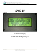
User guide


High Country Tek • Electronic Solutions for Industry
March 28, 2007
© Copyright 2003, High Country Tek Company
All rights reserved. Contents subject to Change
5
Theory of Operation
The DVC61 Smart Display module is
designed to operate from the DVC10
RS-232 port or through the DVC CAN
Bus 2.0B network. The DVC61 could
also be used on any system with an
RS-232 connection and the correct
protocol. Up to 15 DVC61 modules
can be placed on any one DVC system
and one of those can communicate
using an RS-232 connection. When
using the RS-232 connection, the
DVC61 must be connected directly to
the DVC10.
The DVC61 MAC ID, percent
contrast, percent backlight and other
settings are set by connecting the
module directly to a computer through
an RS-232 serial connection and by
using the DVC Program Loader
Monitor (see the DVC Programming
User Guide). Monitoring the DVC61
digital inputs etc. is also achieved
using the DVC Program Loader
Monitor. Note: Contrast and backlight
percentage can also be set by the users’
application program. The users’
application program is created when
using the DVC Programming Tool (see
the DVC Programming User Guide).
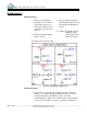
A multitude of screens can be
programmed to display on each
DVC61. When the module is in the
DVC system, up to 12 variables can be
displayed on each screen. The screens
and variables displayed on the DVC61
are set by the users’ application
program. Digital inputs are also setup
by the users’ application program.
Remember, the users’ application
program is created when using the
DVC Programming Tool (see the DVC
Programming User Guide). The users’
application program is loaded into the
DVC10 Master Module. The DVC10
Master Module sends this information
to the DVC61 when the system is in
operation.
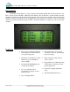
Typical uses of the DVC61 Smart
Display would be to show the status of
inputs or outputs of the DVC system,
or as an indicator when inputs or
outputs of the system reach certain
values. For example, if the engine
exceeded its maximum temperature,
the backlight of the display could flash
on/off and a fault message could
appear.
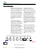
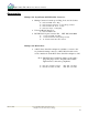
DVC10
MODULE
OUTPUT
UNIVERSAL
CAN BUS
MASTER
MODULE
DVC50
DIGITAL
INPUT
MODULE
DVC21
DVC22
OUTPUT
MODULE
HIGH-SIDE
DVC41
40
DIGITAL
INPUT
MODULE
40
DISPLAY
MODULE
DVC61
DISPLAY
MODULE
DVC61
MEMORY
MODULE
DVC70
DEVICENET
TO
J1939
DVC80
BRIDGE
TO J1939 BUS
RS - 232
Figure 1: DVC System Configuration