
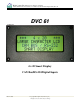
User guide


High Country Tek • Electronic Solutions for Industry
March 28, 2007
© Copyright 2003, High Country Tek Company
All rights reserved. Contents subject to Change
6
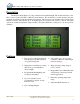
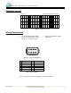
Digital Inputs
Input Operation:
• There are five input pins.
Each pin can be set either
active high, active low, or
both active high and active
low (making a total of 10
inputs).
• Maximum Voltage Range:
0Vdc to 32Vdc
•
Setup is achieved using the
DVC Programming Tool (see
the DVC Programming User
Guide).
• Settings: Toggle/No Toggle
Debounce Time
(0-10.24 seconds in
10 ms increments)
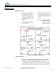
See Figure 1 below for proper wiring.
Figure 2: Sample Input Configurations
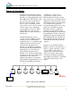
Monitoring Inputs:
• Inputs can be monitored by connecting a DVC61 or DVC10
directly to a computer through an RS-232 connection, and by
using the Program Loader Monitor (refer to the DVC
Programming User Guide). Note: All modules on the CAN Bus
can be monitored when connecting a computer to the DVC10.