
Software User guide

Electronic Controller Solutions for the Global Fluid Power Industry
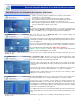
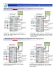
‘P’ and ‘I’ settings:
The P & I setting boxes ( circled in orange, Left ) for each channel are
factory pre-set to P = 10 and I = 10 default values
( = gain/time of ~0.16 )
P & I max values allowed: The window only allows the user to enter from 0
to 255 max values in whole numbers.
The P & I operation in the DVC is scaled such that 255 is equivalent to a gain
of 4, with 64 equaling a gain of 1
These default values allow the majority of proportional coils/valves/pumps to operate normally and meet expected
product OFF to ON and ON to OFF times. Always return to these values if the system needs to be reset.
If it is found that the coil/valves/pumps is not responding as desired, the user may change the values in each box by
selecting the window with the PC mouse and entering a new number.
The ‘P term’ affects the amount of output current change relative to the output current error value that is derived from
the scaling of the command signal to the Imin & Imax settings. Increasing the value makes the change more aggressive
for a smaller error. Too aggressive a change can cause the valve/pump to oscillate ( Under-damped ) , too low a value
setting will result in slow response ( Over-damped ).
The ‘I Term’, affects the output current error correction time . Increasing the value too much can result in the error being
corrected too slowly to matter ( Over-damped ), too small a value can result in corrective current overshoot and multiple
iterations until stable ( Under-damped ).
Settings for P & I are also effected by the system configuration, capacity and even viscosity changes, so the ideal setting
is when the coil being driven responds as the manufacturers specification regarding slew rates for rise and fall times and
delivers the system performance needed for a successful application.
1. Always start running the system using the default P & I settings as supplied to get a base line of operation
2. Use a fast changing command signal with small demand changes to see reaction ( use square wave if possible )
3. If better response is needed, start to increase the ‘P’ setting first, in SMALL increments ( increase by count of 5 )
4. Test system response by using method described in 2. above - readjust as needed to get required response
5. Once the P is set, start to adjust the I setting to get current output stability and system response as required.
NOTE:
Because system characteristics change with oil temperature, viscosity, hose lengths and loading, It is important when
setting P & I values different to the defaults provided, that the user tests the command signal to output stability over a
wide range of settings to ensure the best possible stability and response has been achieved.
P & I Set-up Guide:
10