
Software User guide


Electronic Controller Solutions for the Global Fluid Power Industry
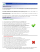
1. Install user interface program onto Windows PC or laptop or HCT TekBook
following the on-screen instructions
2. Connect epc-2 controller to suitable, stabilized power supply (10-32VDC)
3. Connect RS232 communications cable to epc-2 and Windows PC noted in 1
4. Locate the epc-2 program in the PC ‘START’ menu and click to open
5. Once started, the program will open with the screen shown to the left and attempt
to make communications with the epc-2 module
NOTE:
As required, messages will be displayed to alert the user to issues or items that need
attention. Typically GREEN message backgrounds are good while bright RED should
be taken as a warning or notice of a setting or state that could need attention.
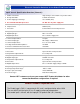
Dual Path epc-2 & evc-2 Graphical User Interface (GUI) Guide:
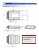
This screen gives the user a ’Dashboard View’ of the controller settings and
operation in one easy to read screen.
The module communications status RX and TX lights will alternate red/green when in
communication, while the module supply voltage and internal temperature can also be
seen in the middle box.
The boxes lower left and right display the ‘Command Input’ and ‘Output Current’ for
channel one and channel two as well as which coil (A or B) is being driven at any time.
The single light bar at bottom middle, will be RED = ‘Driver disabled’ or
GREEN = ‘Driver enabled, to show the status of the global enable input and all
outputs ( proportional AND digital ) on the module.
Clicking the ‘Next >>‘ button will move the user to the next screen or clicking ‘Exit’ will close the interface and return the user to
Windows desktop.
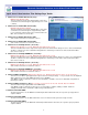
The ‘Configuration Page’ allows the user to set the command signal type to either
DC Voltage (0 to +5VDC) or Current (4 to 20mA) and also to single or dual coiled
valve drive configuration on the pump being controlled.
Selecting a single coil gives the full command signal over the output current, while
selecting a dual coil, immediately offsets the command to give mid value for zero drive
to each coil.
The ‘Current P’ and ‘Current I’ settings allow the user to optimize the response of the
controller to any type or make of valve being driven - see page 11 for guidelines.
Clicking the ‘Next >>‘ button will move the user to the next screen or clicking ‘<< Back’
will take the user to the previous screen.
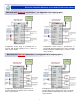
The ‘Fine Tune Page’ offers the user options to customize each channel and to
ensure that the pump reacts as desired and is optimized - see page 6 for details.
As long as the user is connected to a epc-2 module, any changes made here are
transmitted immediately to the module and will change the characteristic in the
non-volatile memory updating the settings and making them the new levels even after
power ON/OFF, so care should be taken to make small changes while also making
sure that the correct parameter is being altered.
User editable value box’s have a blue background with yellow text. Each window has
‘min’ and ‘max’ limits pre-set so prevent the user from entering a value that may cause
issues.
Clicking the ‘Dashboard‘ button will move the user back to the observation screen or clicking ‘<< Back’ will take the user to the
previous screen.
4