
Software User guide

Electronic Controller Solutions for the Global Fluid Power Industry
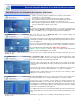
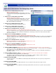
epc-2 & evc-2 User Interface ‘Fine Settings Page’ Guide:
1. Channel X coil 1A Imin Out Current ( mA ):
Minimum value allowed = 0mA
This is the minimum current value that that will be sent to valve
coil 1A when the command signal is approximately ± 5% of 2.5V
(~125mV)
2. Channel X coil 1A Imax Out Current (mA):
Maximum value allowed = 3000mA
This is the maximum current value that that will be sent to valve
coil 1A when the command signal is at approximately ±100%
i.e. 0% command = Coil B at 100%, 50% command - Both coils
OFF, 100% command = Coil A at 100%.
3. Channel X coil 1B Imin Out Current (mA):
Same function and action as noted in item 1. above
4. Channel X coil 1B Imax Out Current (mA):
Same function and action as noted in item 2. above
5. Channel X coil 1A Ramp UP time ( Seconds ):
Minimum value allowed = 0 seconds - Maximum value allowed = 65 seconds
This is the total time taken for the output current to go between the Imin and Imax settings for a 0% to 100% command input.
The time is scaled for 0 to 100% command meaning that if the command goes from 50% to 100% the time taken will be
50% of the seconds set.
6. Channel X coil 1A Ramp DOWN time ( Seconds ):
Minimum value allowed = 0 seconds - Maximum value allowed = 65 seconds
This is the total time taken for the output current to go between the Imax and Imin settings for a 100% to 0% command input.
The time is scaled for 0 to 100% command meaning that if the command goes from 100% to 50% the time taken will be
50% of the seconds set.
7. Channel X coil 1B Ramp UP time ( Seconds ):
Minimum value allowed = 0 seconds - Maximum value allowed = 65 seconds
Same function and action as noted in item 5. above
8. Channel X coil 1B Ramp DOWN time ( Seconds ):
Minimum value allowed = 0 seconds - Maximum value allowed = 65 seconds
Same function and action as noted in item 6. above
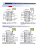
9. Channel X Dither Amplitude: Minimum value allowed = 0% - Maximum value allowed = 100% ( in 10% increments )
This is the level of ‘Dither’ signal applied to the output current as a fixed percentage - i.e. if you set 50% here, the amplitude
will be ratiometric over the entire PWM output range of 5 to 95 PWM.
Valve OEM’s usually recommend a % level here If no information is available, set to 30% for initial trials and optimize at
later stage if needed.
10. Channel X Dither Frequency ( Hz ): pre-set values - 33, 45, 50, 55, 76, 100, 125, 142, 200, 250, 333 & 500HZ
This is the ‘Dither’ frequency that will be on the PWM output.
Valve OEM’s usually recommend a frequency here, if no information is available, initially set 140Hz - 250Hz for
cartridge and smaller valves and 100Hz - 140Hz for larger industrial valves.
11. Channel X Command Min:
The value entered here, sets the Minimum command input allowed. Below this value, the respective epc-2 proportional
output is disabled
12. Channel X Command Mid:
The value entered here, sets the Mid command for crossover in dual coil mode, ignored for single coil mode
13. Channel X Command Max:
The value entered here, sets the Maximum command input allowed. Above this value, the respective epc-2 proportional
output is disabled
6