Network Video Recorder User Manual UD04699B
Network Video Recorder User Manual User Manual COPYRIGHT © 2017 Hangzhou Hikvision Digital Technology Co., Ltd. ALL RIGHTS RESERVED. Any and all information, including, among others, wordings, pictures, graphs are the properties of Hangzhou Hikvision Digital Technology Co., Ltd. or its subsidiaries (hereinafter referred to be “Hikvision”).
Network Video Recorder User Manual Regulatory Information FCC Information Please take attention that changes or modification not expressly approved by the party responsible for compliance could void the user’s authority to operate the equipment. FCC compliance: This equipment has been tested and found to comply with the limits for a Class A digital device, pursuant to part 15 of the FCC Rules.
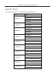
Network Video Recorder User Manual Applicable Models This manual is applicable to the models listed in the following table.
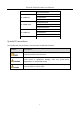
Network Video Recorder User Manual DS-7732NI-K4/16P DS-7608NI-K2 DS-7600NI-K2 DS-7616NI-K2 DS-7632NI-K2 DS-7608NI-K2/8P DS-7600NI-K2/P DS-7616NI-K2/16P DS-7632NI-K2/16P DS-7604NI-K1 DS-7600NI-K1 DS-7608NI-K1 DS-7616NI-K1 DS-7600NI-K1/4P DS-7604NI-K1/4P Symbol Conventions The symbols that may be found in this document are defined as follows. Symbol Description Provides additional information to emphasize or supplement important points of the main text.
Network Video Recorder User Manual Safety Instructions Proper configuration of all passwords and other security settings is the responsibility of the installer and/or end-user. In the use of the product, you must be in strict compliance with the electrical safety regulations of the nation and region. Please refer to technical specifications for detailed information.
Network Video Recorder User Manual Product Key Features General Connectable to network cameras, network dome and encoders. Connectable to the third-party network cameras like ACTI, Arecont, AXIS, Bosch, Brickcom, Canon, PANASONIC, Pelco, SAMSUNG, SANYO, SONY, Vivotek and ZAVIO, and cameras that adopt ONVIF or PSIA protocol. Connectable to the smart IP cameras. H.265+/H.265/ H.264+/H.264/MPEG4 video formats PAL/NTSC adaptive video inputs. Each channel supports dual-stream.
Network Video Recorder User Manual Up to 6TB storage capacity for each disk supported. Supports 8 network disks (NAS/IP SAN disk). Supports S.M.A.R.T. and bad sector detection. HDD group management. Supports HDD standby function. HDD property: redundancy, read-only, read/write (R/W). HDD quota management; different capacity can be assigned to different channel. For DS-9600NI-I8 and DS-9600NI-I16 series, RAID0, RAID1, RAID5, RAID6 and RAID 10 are supported.
Network Video Recorder User Manual Supports pause, play reverse, speed up, speed down, skip forward, and skip backward when playback, and locating by dragging the mouse. Supports thumbnails view and fast view during playback. Up to 16-ch synchronous playback at 1080p real time. Supports playback by transcoded stream. Manual capture, continuous capture of video images and playback of captured pictures. Supports enabling H.264+ to ensure high video quality with lowered bitrate.
Network Video Recorder User Manual Network Functions Two self-adaptive 10M/100M/1000Mbps network interfaces for DS-9600NI, DS-8600NI, DS-7700NI-I4 and DS-7700NI-K4, and the multi-address and network fault tolerance working modes are configurable. One self-adaptive 10M/100M/1000Mbps network interface for DS-7600NI-K2/I2 (/P), DS-7700NI-I4/P and DS-7700NI-K4/P. One self-adaptive 10M/100Mbps network interface for DS-7600NI-K1 (/P).
Network Video Recorder User Manual Embedded WEB server. Development Scalability: SDK for Windows system. Source code of application software for demo. Development support and training for application system.
Network Video Recorder User Manual TABLE OF CONTENTS Chapter 1 Introduction ................................................................................................................... 18 1.1 Front Panel ....................................................................................................................... 18 1.1.1 DS-9600NI Series ..................................................................................................... 18 1.1.2 DS-8600NI-I8 Series .......................
Network Video Recorder User Manual 3.2.3 Using an Auxiliary Monitor...................................................................................... 73 3.2.4 Quick Setting Toolbar in Live View Mode ............................................................... 74 3.2.5 Fisheye Expansion View .......................................................................................... 76 3.3 Adjusting Live View Settings ......................................................................................
Network Video Recorder User Manual 6.1.3 Playing back by Smart Search................................................................................ 122 6.1.4 Playing Back by Event Search ................................................................................ 125 6.1.5 Playing Back by Tag ............................................................................................... 127 6.1.6 Playing Back by Sub-periods ..............................................................................
Network Video Recorder User Manual 9.3 Configuring POS Privacy Information Filtering............................................................... 170 9.4 Configuring POS Alarm ................................................................................................... 170 Chapter 10 VCA Alarm ................................................................................................................ 173 10.1 Face Detection.........................................................................
Network Video Recorder User Manual 12.4 Configuring Network Detection ................................................................................... 212 12.4.1 Testing Network Delay and Packet Loss .............................................................. 212 12.4.2 Exporting Network Packet ................................................................................... 212 12.4.3 Checking the Network Status .............................................................................. 213 12.
Network Video Recorder User Manual 16.4 Importing/Exporting Configuration Files ..................................................................... 252 16.5 Upgrading System......................................................................................................... 253 16.5.1 Upgrading by Local Backup Device...................................................................... 253 16.5.2 Upgrading by FTP .........................................................................................
Network Video Recorder User Manual Version 3.4.90................................................................................................................. 304 Version 3.4.80................................................................................................................. 304 Version 3.4.70................................................................................................................. 305 Version 3.4.6....................................................................
Network Video Recorder User Manual Chapter 1 Introduction 1.1 Front Panel 1.1.
Network Video Recorder User Manual Table 1-1 Panel Description No. Name Function Description ALARM Turns red when a sensor alarm is detected. READY Turns blue when the device is functioning properly. Turns blue when device is controlled by an IR remote. STATUS 1 Status Indicators Turns red when controlled by a keyboard and purple when IR remote and keyboard is used at the same time. HDD Flickers red when data is being read from or written to HDD. MODEM Reserved for future usage.
Network Video Recorder User Manual No. Name Function Description 6 Universal Serial Bus (USB) ports for additional devices such as USB mouse and USB Hard Disk Drive (HDD). USB Interfaces Returns to the previous menu. ESC Presses for arming/disarming the device in live view mode. Enters the Manual Record settings menu. REC/SHOT Presses this button followed by a numeric button to call a PTZ preset in PTZ control settings. Turns audio on/off in the playback mode.
Network Video Recorder User Manual No. Name Function Description Turns on/off PTZ light (if applicable) in PTZ control mode. Switches between play and reverse play in playback mode. Cycles through tab pages. F2/ AUX Switches between channels in synchronous playback mode. Returns to the Main menu (after successful login). MENU/WIPER Presses and holds the button for five seconds to turn off audible key beep. Starts wiper (if applicable) in PTZ control mode.
Network Video Recorder User Manual No. Name Function Description mode. Advances the video by a single frame in single-frame playback mode. Stops/starts auto switch in auto-switch mode. Moves the active selection up and down in a menu. 9 JOG SHUTTLE Control Cycles through different channels in live view mode. Jumps 30s forward/backward in video files in the playback mode. Controls the movement of the PTZ camera in PTZ control mode.
Network Video Recorder User Manual Table 1-2 Description of Control Panel Buttons No. Name Function Description ALARM Turns red when a sensor alarm is detected. READY Turs blue when the device is functioning properly. Turns blue when device is controlled by an IR remote. STATUS 1 Status Indicators Turns red when controlled by a keyboard and purple when IR remote and keyboard is used at the same time. HDD Flickers red when data is being read from or written to HDD.
Network Video Recorder User Manual No. Name Function Description Drive (HDD). Returns to the previous menu. ESC Presses for arming/disarming the device in live view mode. Enters the Manual Record settings menu. REC/SHOT Presses this button followed by a numeric button to call a PTZ preset in PTZ control settings. Turns audio on/off in the playback mode. PLAY/AUTO ZOOM+ Enters the playback mode. Automatically scans in the PTZ control menu. Zooms in the PTZ camera in the PTZ control setting.
Network Video Recorder User Manual No. Name Function Description playback mode. Cycles through tab pages. F2/ AUX Switches between channels in synchronous playback mode. Returns to the Main menu (after successful login). MENU/WIPER Presses and holds the button for five seconds to turn off audible key beep. Starts wiper (if applicable) in PTZ control mode. Shows/hides the control interface in playback mode. PREV/FOCUS- Switches between single screen and multi-screen mode.
Network Video Recorder User Manual No. Name Function Description Stops/starts auto switch in auto-switch mode. Moves the active selection up and down in a menu. 8 JOG SHUTTLE Control Cycles through different channels in live view mode. Jumps 30s forward/backward in video files in the playback mode. Controls the movement of the PTZ camera in PTZ control mode. 9 POWER ON/OFF Power on/off switch. 1.1.
Network Video Recorder User Manual Table 1-3 Panel Description No. Name 1 Status Indicators Function Description POWER Turns green when NVR is powered up. HDD Blinks red when HDD is reading/writing. Tx/Rx Blinks green when network connection is functioning normally. The Enter button is used to confirm selection in menu mode; or used to check checkbox fields and ON/OFF switch. In playback mode, it can be used to play or pause the video.
Network Video Recorder User Manual 1.1.4 DS-7600NI Series Figure 1-6 DS-7600NI Series Table 1-4 Panel Description No. Name Connections 1 POWER Turns green when NVR is powered up. 2 HDD Flickers red when data is being read from or written to HDD. 3 Tx/Rx Flickers blue when network connection is functioning properly. 4 USB Interface Universal Serial Bus (USB) port for additional devices such as USB mouse and USB Hard Disk Drive (HDD). 1.
Network Video Recorder User Manual Step 4 Press the DEV button. Step 5 Use the Number buttons to enter the Device ID# that was entered into the NVR. Step 6 Press Enter button to accept the new Device ID#. Figure 1-7 Remote Control Unpairing (Disabling) an IR Remote from a NVR To unpair an IR Remote from a NVR so that the unit cannot control any NVR functions, proceed as follows: Press the DEV key on the IR Remote.
Network Video Recorder User Manual Table 1-5 IR Remote Functions No. Name Function Description • To Turn Power On: - If User Has Not Changed the Default NVR Device ID# (255): 1. Press Power On/Off button (1). - If User Has Changed the NVR Device ID#: 1. Press DEV button. 2. Press Number buttons to enter user-defined Device ID#. 3. Press Enter button. 4. Press Power button to start device. • To Turn NVR Off: - If User Is Logged On: 1.
Network Video Recorder User Manual User name/password prompt depends on NVR is configuration. See “System Configuration” section.
Network Video Recorder User Manual Control PTZ camera movement in PTZ control mode Confirm selection in any menu mode Checks checkbox ENTER Play or pause video in Playback mode Advance video a single frame in single-frame Playback mode Stop/start auto switch in auto-switch mode 13 PTZ 14 ESC 15 RESERVED Enter PTZ Control mode Go back to previous screen N/A Reserved Select all items on a list 16 F1 N/A Switch between play and reverse play in Playback mode 17 PTZ Control 18 F2 Adjust PTZ camer
Network Video Recorder User Manual If the Status indicator on the front panel turns blue, the remote control is operating properly. If the Status indicator does not turn blue and there is still no response from the remote, please check the following: Batteries are installed correctly and the polarities of the batteries are not reversed. Batteries are fresh and not out of charge. IR receiver is not obstructed.
Network Video Recorder User Manual 1.3 USB Mouse Operation A regular 3-button (Left/Right/Scroll-wheel) USB mouse can also be used with this NVR. To use a USB mouse: Step 1 Plug USB mouse into one of the USB interfaces on the front panel of the NVR. Step 2 The mouse should automatically be detected. If in a rare case that the mouse is not detected, the possible reason may be that the two devices are not compatible, please refer to the recommended the device list from your provider.
Network Video Recorder User Manual 1.
Network Video Recorder User Manual 1.5 Rear Panel 1.5.
Network Video Recorder User Manual Table 1-8 Panel Description No. Name Description 1 LAN1/LAN2 Interface 2 RJ-45 10/100/1000 Mbps self-adaptive Ethernet interfaces provided. 2 LINE IN RCA connector for audio input. 3 AUDIO OUT 2 RCA connectors for audio output. 4 HDMI1/HDMI2 HDMI video output connector. 5 VGA1/VGA2 DB9 connector for VGA output. Display local video output and menu. 6 USB 3.
Network Video Recorder User Manual Figure 1-13 DS-7600NI-I2/8P and DS-7600NI-K2/8P Series The DS-7616NI-I2/16P and DS-7632NI-I2/16P provide 16 network Interfaces with PoE function. Table 1-9 Panel Description No. Name Description 1 Audio In RCA connector for audio input. 2 Audio Out RCA connector for audio output. 3 VGA Interface DB9 connector for VGA output. Display local video output and menu. 4 HDMI Interface HDMI video output connector. 5 ALARM IN Connector for alarm input.
Network Video Recorder User Manual (supported DS-7600NI-I2/P) by DS-7600NI-K1 and DS-7600NI-K1/4P Figure 1-14 DS-7600NI-K1 Series Figure 1-15 DS-7604NI-K1/4P Series Table 1-10 Panel Description No. Name Description 1 Network Interfaces Network interfaces for the cameras and to provide with PoE function power over Ethernet. 2 Audio In RCA connector for audio input. 3 Audio Out RCA connector for audio output. 4 VGA Interface DB9 connector for VGA output. Display local video output and menu.
Network Video Recorder User Manual 10 Ground Ground (needs to be connected when NVR starts up). 1.5.3 DS-7700NI Series Figure 1-16 DS-7700NI-I4 and DS-7700NI-K4 Series Figure 1-17 DS-7700NI-I4/16P and DS-7700NI-K4/16P Series The DS-7708NI-I4/8P and DS-7708NI-K4/8P provides 8 network Interfaces with PoE function. Table 1-11 Panel Description No.
Network Video Recorder User Manual 7 VGA DB9 connector for VGA output. Display local video output and menu. 8 RS-485 Interface Half-duplex connector for RS-485 devices. 9 ALARM IN Connector for alarm input. ALARM OUT Connector for alarm output. 10 GROUND Ground (needs to be connected when NVR starts up). 11 AC 100V ~ 240V 100V to 240VAC power supply. 12 Power Switch Switch for turning on/off the device.
Network Video Recorder User Manual Chapter 2 Getting Started 2.1 Device Startup and Activation 2.1.1 Starting Up and Shutting Down the NVR Purpose: Proper startup and shutdown procedures are crucial to expanding the life of the NVR. Before you start: Check that the voltage of the extra power supply is the same with the NVR’s requirement, and the ground connection is working properly. Starting up the NVR: Step 1 Check the power supply is plugged into an electrical outlet.
Network Video Recorder User Manual Step 3 Click the Yes button. OPTION 2: By operating the front panel Step 1 Press and hold the POWER button on the front panel for 3 seconds. Step 2 Enter the administrator’s username and password in the dialog box for authentication. Step 3 Click the Yes button. Do not press the POWER button again when the system is shutting down. Rebooting the NVR In the Shutdown menu, you can also reboot the NVR. Step 1 Enter the Shutdown menu by clicking Menu > Shutdown.
Network Video Recorder User Manual We highly recommend you create a strong password of your own choosing (Using a minimum of 8 characters, including at least three of the following categories: upper case letters, lower case letters, numbers, and special characters.) in order to increase the security of your product. And we recommend you reset your password regularly, especially in the high security system, resetting the password monthly or weekly can better protect your product.
Network Video Recorder User Manual If Admin’s password is modified, the following menu pops up. Optionally, click the Yes button to duplicate the password to IP cameras that are connected with default protocol. Figure 2-5 Attention Interface 2.1.3 Using the Unlock Pattern for Login For the Admin user, you can configure the unlock pattern for device login. Configuring the Unlock Pattern Step 1 After the device is activated, you can enter the following interface to configure the device unlock pattern.
Network Video Recorder User Manual Figure 2-7 Draw the Pattern Connect at least 4 dots to draw the pattern. Each dot can be connected for once only. Step 3 Draw the same pattern again to confirm it. When the two patterns match, the pattern is configured successfully. Figure 2-8 Confirm the Pattern If the two patterns are different, you must set the pattern again.
Network Video Recorder User Manual Figure 2-9 Re-set the Pattern Logging in via Unlock Pattern Only the admin user has the permission to unlock the device. Please configure the pattern first before unlocking. Please refer to Configuring the Unlock Pattern Step 1 Right click the mouse on the screen and select the menu to enter the interface as shown in Figure 2.8. Figure 2-10 Draw the Unlock Pattern Step 2 Draw the pre-defined pattern to unlock to enter the menu operation.
Network Video Recorder User Manual If you have forgotten your pattern, you can select the Forget My Pattern or Switch User option to enter the normal login dialog box. When the pattern you draw is different from the pattern you have configured, you should try again. If you have drawn the wrong pattern for more than 5 times, the system will switch to the normal login mode automatically. Figure 2-11 Normal Login Dialog Box 2.1.
Network Video Recorder User Manual In the Login dialog box, if you enter the wrong password 7 times, the current user account will be locked for 60 seconds. User Logout Purpose: After logging out, the monitor turns to the live view mode and if you want to perform any operations, you need to enter user name and password log in again. Step 1 Enter the Shutdown menu. Menu > Shutdown Figure 2-13 Logout Step 2 Click Logout. After you have logged out the system, menu operation on the screen is invalid.
Network Video Recorder User Manual Figure 2-14 Reset Password Step 2 Select the GUID file from the U flash disk and click Import to import the file to the device. If you have imported the wrong GUIE file for 7 times, you will be not allowed to reset the password for 30 minutes. Step 3 After the GUID file is successfully imported, enter the reset password interface to set the new admin password. Refer to Chapter 2.1.2 Activating Your Device for details. Step 4 Click OK to set the new password.
Network Video Recorder User Manual Figure 2-15 Start Wizard Interface Operating the Setup Wizard: Step 1 The Setup Wizard can walk you through some important settings of the NVR. If you don’t want to use the Setup Wizard at that moment, click the Cancel button. You can also choose to use the Setup Wizard next time by leaving the “Start wizard when the device starts?” checkbox checked. Step 2 Click Next button to enter the date and time settings window, as shown in Figure 2-16.
Network Video Recorder User Manual Figure 2-17 Network Settings Two self-adaptive 10M/100M/1000M network interfaces provided for DS-9600NI, DS-8600NI, DS-7700NI-I4 and DS-7700NI-K4, and two working modes are configurable: multi-address and network fault tolerance. And one self-adaptive 10M/100M/1000M network interface for DS-7600NI, DS-7700NI-I4/P and DS-7700NI-K4/P. Step 4 Click Next button after you configured the basic network parameters. Enter the Hik-Connect interface to configure the parameters.
Network Video Recorder User Manual Figure 2-19 Advanced Network Parameters Step 6 Click Next button after you configured the network parameters, which takes you to the RAID configuration window. The RAID is supported by DS-9600NI-I8 and DS-9600NI-I16 series NVR only. Figure 2-20 Array Management Step 7 Click Next button to enter the Array Management window.
Network Video Recorder User Manual Figure 2-21 Array Management Step 8 Click Next button after you configured the network parameters, which takes you to the HDD Management window, shown in Figure 2-22. Figure 2-22 HDD Management Step 9 To initialize the HDD, click the Init button. Initialization removes all the data saved in the HDD. Step 10 Click Next button. You enter the Adding IP Camera interface.
Network Video Recorder User Manual Figure 2-23 Search for IP Cameras When you check the checkbox of Enable H.265, the NVR can automatically switch to the H.265 stream of IP camera (which supports H.265 video format) for the initial access. Step 12 Click Next button. Configure the recording for the added IP Cameras. Figure 2-24 Record Settings Step 13 Click OK to complete the startup Setup Wizard.
Network Video Recorder User Manual 2.3 Adding and Connecting the IP Cameras 2.3.1 Activating the IP Camera Purpose: Before adding the camera, make sure the IP camera to be added is in active status. Step 1 Select the Add IP Camera option from the right-click menu in live view mode or click Menu> Camera> Camera to enter the IP camera management interface. For the IP camera detected online in the same network segment, the Password status shows whether it is active or inactive.
Network Video Recorder User Manual Step 3 Set the password of the camera to activate it. Use Admin Password: when you check the checkbox, the camera (s) will be configured with the same admin password of the operating NVR. Figure 2-27 Set New Password Create New Password: If the admin password is not used, you must create the new password for the camera and confirm it.
Network Video Recorder User Manual Step 2 Click the icon in the center of the windw to pop up the adding IP camera interface. Figure 2-28 Icon of Adding IP Camera Step 3 Select the detected IP camera and click the Add button to add it directly, and you can click the Search button to refresh the online IP camera manually.
Network Video Recorder User Manual Figure 2-30 Adding IP Camera Interface Step 2 The online cameras with same network segment will be detected and displayed in the camera list. Step 3 Select the IP camera from the list and click the button to add the camera. Or you can click the One-touch Adding button to add all cameras (with the same login password) from the list. Make sure the camera to add has already been activated.
Network Video Recorder User Manual OPTION 3: Step 1 On the IP Camera Management interface, click the Custom Adding button to pop up the Add IP Camera (Custom) interface. Figure 2-32 Custom Adding IP Camera Interface Step 2 You can edit the IP address, protocol, management port, and other information of the IP camera to be added. If the IP camera to add has not been actiavated, you can activate it from the IP camera list on the camera management interface.
Network Video Recorder User Manual Table 2-1 Description of Icons Icon Explanation Icon Explanation Edit basic parameters of the camera Add the detected IP camera. The camera is disconnected; you can click the icon to get the exception information of camera. Delete the IP camera Play the live video of the connected camera. Advanced settings of the camera.
Network Video Recorder User Manual Figure 2-34 List of Added IP Cameras Enabling the H.265 Stream Access You can check the checkbox of Enable H.265, the NVR can automatically switch to the H.265 stream of IP camera (which supports H.265 video format) for the initial access. 2.3.3 Editing the Connected IP Cameras and Configuring Customized Protocols After the adding of the IP cameras, the basic information of the camera lists in the page, you can configure the basic setting of the IP cameras.
Network Video Recorder User Manual Figure 2-35 Edit the Parameters Channel Port: If the connected device is an encoding device with multiple channels, you can choose the channel to connect by selecting the channel port No. in the dropdown list. Step 2 Click OK to save the settings and exit the editing interface. To edit advanced parameters: Step 1 Drag the horizontal scroll bar to the right side and click the icon.
Network Video Recorder User Manual Figure 2-37 Password Configuration of the Camera Step 3 Click OK to save the settings and exit the interface. Configuring the customized protocols Purpose: To connect the network cameras which are not configured with the standard protocols, you can configure the customized protocols for them. Step 1 Click the Protocol button in the custom adding IP camera interface to enter the protocol management interface.
Network Video Recorder User Manual Before customizing the protocol for the network camera, you have to contact the manufacturer of the network camera to consult the URL (uniform resource locator) for getting main stream and sub-stream. The format of the URL is: [Type]://[IP Address of the network camera]:[Port]/[Path]. Example: rtsp://192.168.1.55:554/ch1/main/av_stream. Protocol Name: Edit the name for the custom protocol.
Network Video Recorder User Manual 2.3.4 Editing IP Cameras Connected to the PoE Interfaces This chapter is only applicable for the following models: DS-7600NI-I2/P, DS-7700NI-I4/P, DS-7600NI-K2/P, DS-7700NI-K4/P and DS-7600NI-K1/4P series NVR. The PoE interfaces enables the NVR system to pass electrical power safely, along with data, on Ethernet cabling to the connected network cameras.
Network Video Recorder User Manual edited in the Network Configuration interface, see Chapter 11.1 Settings for detailed information. Configuring General Figure 2-41 Edit IP Camera Interface - Plug-and-Play • Manual: You can disable the PoE interface by selecting the manual while the current channel can be used as a normal channel and the parameters can also be edited. Input the IP address, the user name and password of administrator manually, and click OK to add the IP camera.
Network Video Recorder User Manual 2.3.5 Configuring PoE Interface When it requires long-distance PoE transmission (100 to 300 m), you can configure the PoE channel to the long network cable mode. Step 1 Enter the PoE Configuration interface. Menu> Camera> Camera>PoE Configuration Step 2 Click the radio button of each POE channel to switch and . You can click the radio button of PoE Channel to enable or disable the long network cable mode.
Network Video Recorder User Manual The PoE is enabled with the short network cable mode (OFF) by default. The bandwidth of IP camera connected to the PoE via long network cable (100 - 300 meters) cannot exceed 6 MP. The allowed max. long network cable may be less than 300 meters depending on different IP camera models and cable materials. When the transmission distance reaches 100 to 250 meters, you must use the CAT5E or CAT6 network cable to connect with the PoE interface.
Network Video Recorder User Manual Chapter 3 Live View 3.1 Introduction of Live View Live view shows you the video image getting from each camera in real time. The NVR automatically enters Live View mode when powered on. It is also at the very top of the menu hierarchy, thus pressing the ESC many times (depending on which menu you’re on) brings you to the Live View mode.
Network Video Recorder User Manual 3.2 Operations in Live View Mode In live view mode, there are many functions provided. The functions are listed below. • Single Screen: showing only one screen on the monitor. • Multi-screen: showing multiple screens on the monitor simultaneously. • Auto-switch: the screen is auto switched to the next one. And you must set the dwell time for each screen on the configuration menu before enabling the auto-switch. Menu>Configuration>Live View>Dwell Time.
Network Video Recorder User Manual 3.2.1 Front Panel Operation on Live View Table 3-2 Front Panel Operation in Live View Functions Front Panel Operation Show single screen Press the corresponding Alphanumeric button. E.g. Press 2 to display only the screen for channel 2. Show multi-screen Press the PREV/FOCUS- button. Manually screens Previous screen: left/up direction button. switch Next screen: right/down direction button. Auto-switch Press Enter button. Playback Press Play button.
Network Video Recorder User Manual PTZ Enter the PTZ control interface. Output Mode Four modes of output supported, including Standard, Bright, Gentle and Vivid. Aux Monitor Switch to the auxiliary output mode and the operation for the main output is disabled. The dwell time of the live view configuration must be set before using Start Auto-switch.
Network Video Recorder User Manual Main Monitor: Enter Main operation mode. In the live view mode of the main output monitor, the menu operation is not available while Aux output mode is enabled. 3.2.4 Quick Setting Toolbar in Live View Mode On the screen of each channel, there is a quick setting toolbar which shows when you single click the mouse in the corresponding screen.
Network Video Recorder User Manual Digital Zoom is for zooming in the live image. You can zoom in the image to different proportions (1 to16X) by moving the sliding bar from to . You can also scroll the mouse wheel to control the zoom in/out. Figure 3-3 Digital Zoom Image Settings icon can be selected to enter the Image Settings menu. You can set the image parameters like brightness, contrast, saturation and hue according to the actual demand.
Network Video Recorder User Manual Figure 3-5 Live View Strategy Face detection function can be used to detect the human faces in live view mode and save in HDD. When there are human faces with the specified size detected in the front of the camera, the device will capture the human face and save in HDD. Move the mouse onto the icon to show the real-time stream information, including the frame rate, bitrate, resolution and stream type. Figure 3-6 Information 3.2.
Network Video Recorder User Manual Table 3-5 Fisheye Display Mode Button Operation 180° panorama Fisheye expansion 360° panorama PTZ expansion Fisheye Four different display modes are available. You can select a display mode as demand. 180° Panorama: Switch the live view image to the 180° panorama view. 360° Panorama: Switch the live view image to the 360° panorama view.
Network Video Recorder User Manual 3.3 Adjusting Live View Settings Purpose: Live View settings can be customized according to different needs. You can configure the output interface, dwell time for screen to be shown, mute or turning on the audio, the screen number for each channel, etc. Step 1 Enter the Live View Settings interface.
Network Video Recorder User Manual Figure 3-8 Live View- Camera Order 1) Select a View mode in , including 1/4/6/8/16/25/32/36/64-window division modes are supported depending on different models. 2) Select the small window, and double-click on the channel number to display the channel on the window. 3) You can click button to start live view for all the channels and click live view. 4) Click the Apply button to save the setting.
Network Video Recorder User Manual 3.4 Channel-zero Encoding Purpose: Sometimes you need to get a remote view of many channels in real time from web browser or CMS (Client Management System) software, in order to decrease the bandwidth requirement without affecting the image quality, channel-zero encoding is supported as an option for you. Step 1 Enter the Live View Settings interface. Menu > Configuration> Live View Step 2 Select the Channel-Zero Encoding tab.
Network Video Recorder User Manual Chapter 4 PTZ Controls 4.1 Configuring PTZ Settings Purpose: Follow the procedure to set the parameters for PTZ. The configuring of the PTZ parameters should be done before you control the PTZ camera. Step 1 Enter the PTZ Settings interface. Menu >Camera> PTZ Figure 4-1 PTZ Settings Step 2 Click the PTZ Parameters button to set the PTZ parameters.
Network Video Recorder User Manual Step 3 Choose the camera for PTZ setting in the Camera dropdown list. Step 4 Enter the parameters of the PTZ camera. All the parameters should be exactly the same as the PTZ camera parameters. Step 5 Click Apply button to save the settings.
Network Video Recorder User Manual 4.2 Setting PTZ Presets, Patrols & Patterns Before you start: Please make sure that the presets, patrols and patterns should be supported by PTZ protocols. 4.2.1 Customizing Presets Purpose: Follow the steps to set the Preset location which you want the PTZ camera to point to when an event takes place. Step 1 Enter the PTZ Control interface.
Network Video Recorder User Manual This feature enables the camera to point to a specified position such as a window when an event takes place. Step 1 Click the button PTZ in the lower-right corner of the PTZ setting interface; Or press the PTZ button on the front panel or click the PTZ Control icon in the quick setting bar, or select the PTZ option in the right-click menu to show the PTZ control panel. Step 2 Choose Camera in the dropdown list.
Network Video Recorder User Manual Figure 4-5 PTZ Settings Step 2 Select patrol No. in the drop-down list of patrol. Step 3 Click the Set button to add key points for the patrol. Figure 4-6 Key point Configuration Step 4 Configure key point parameters, such as the key point No., duration of staying for one key point and speed of patrol. The key point is corresponding to the preset. The Key Point No. determines the order at which the PTZ will follow while cycling through the patrol.
Network Video Recorder User Manual Or press the PTZ button on the front panel or click the PTZ Control icon in the quick setting bar, or select the PTZ option in the right-click menu to show the PTZ control panel. Step 2 Click the button to show the general settings of the PTZ control. Figure 4-7 PTZ Panel - General Step 3 Select a patrol in the dropdown list and click the Call Patrol button to call it. Step 4 You can click the Stop Patrol button to stop calling it. 4.2.
Network Video Recorder User Manual Step 3 Click the Start button and click corresponding buttons in the control panel to move the PTZ camera, and click the Stop button to stop it. The movement of the PTZ is recorded as the pattern. 4.2.6 Calling Patterns Purpose: Follow the procedure to move the PTZ camera according to the predefined patterns.
Network Video Recorder User Manual Figure 4-10 PTZ Settings Step 2 Use the directional button to wheel the camera to the location where you want to set the limit, and click the Left Limit or Right Limit button to link the location to the corresponding limit. The speed dome starts linear scan from the left limit to the right limit, and you must set the left limit on the left side of the right limit, as well the angle from the left limit to the right limit should be no more than 180º. 4.2.
Network Video Recorder User Manual Figure 4-11 PTZ Panel - One-touch Step 3 Click Linear Scan button to start the linear scan and click the Linear Scan button again to stop it. You can click the Restore button to clear the defined left limit and right limit data and the dome needs to reboot to make settings take effect. 4.2.9 One-touch Park Before operating this function, make sure the connected camera supports the linear scan and is in HIKVISION protocol.
Network Video Recorder User Manual Step 3 There are 3 one-touch park types selectable, click the corresponding button to activate the park action. Park (Quick Patrol): The dome starts patrol from the predefined preset 1 to preset 32 in order after the park time. The undefined preset will be skipped. Park (Patrol 1): The dome starts move according to the predefined patrol 1 path after the park time. Park (Preset 1): The dome moves to the predefined preset 1 location after the park time.
Network Video Recorder User Manual 4.3 PTZ Control Panel To enter the PTZ control panel, there are two ways supported. OPTION 1: In the PTZ settings interface, click the PTZ button on the lower-right corner which is next to the Back button. OPTION 2: In the Live View mode, you can press the PTZ Control button on the front panel or on the remote control, or choose the PTZ Control icon , or select the PTZ option in the right-click menu.
Network Video Recorder User Manual Table 4-1 Description of the PTZ panel icons Icon Description Icon Description Icon Description Direction button and the auto-cycle button Zoom+, Focus+, Iris+ Zoom-, Focus-, Iris- The speed of the PTZ movement Light on/off Wiper on/off 3D Positioning Image Centralization Menu Switch to the PTZ control interface Switch to the one-touch control interface Switch to the general settings interface Previous item Next item Start pattern / patrol Stop the pat
Network Video Recorder User Manual Chapter 5 Recording and Capture Settings The picture capture is supported by the DS-7600/7700/8600/9600-I (/P) series NVR only. 5.1 Configuring Parameters Purpose: By configuring the parameters you can define the parameters which affect the image quality, such as the transmission stream type, the resolution and so on. Before you start: 1) Make sure that the HDD has already been installed. If not, please install a HDD and initialize it.
Network Video Recorder User Manual Figure 5-3 Recording Parameters Step 2 Parameters Setting for Recording 1) Select Record tab page to configure. You can configure the stream type, the resolution, and other parameters on your demand. Video Encode: select the video encoding to H.265 or H.264. Enable H.264+ Mode: check the checkbox to enable. Once enabled, the Max. Bitrate Mode, Max. Bitrate(Kbps) and Max. Bitrate Range Recommend are not configurable.
Network Video Recorder User Manual Pre-record: The time you set to record before the scheduled time or event. For example, when an alarm triggers the recording at 10:00, and if you set the pre-record time as 5 seconds, the camera records at 9:59:55. Post-record: The time you set to record after the event or the scheduled time. For example, when an alarm triggered recording ends at 11:00, and if you set the post-record time as 5 seconds, it records till 11:00:05.
Network Video Recorder User Manual Figure 5-5 Sub-stream Parameters 2) Configure the parameters of the camera. 3) Click Apply to save the settings. Step 4 Parameters Settings for Capture 1) Select the Capture tab. Figure 5-6 Capture Parameters 2) Configure the parameters. 3) Click Apply to save the settings. The interval is the time period between two capturing actions. You can configure all the parameters on this menu on your demand.
Network Video Recorder User Manual 5.2 Configuring Recording and Capture Schedule Purpose: Set the record schedule, and then the camera automatically starts/stops recording according to the configured schedule. In this chapter, we take the record schedule procedure as an example, and the same procedure can be applied to configure schedule for both recording and capture. To schedule the automatic capture, you need to choose the Capture tab in the Schedule interface.
Network Video Recorder User Manual M&A: recording triggered by motion detection and alarm. POS: recording triggered by POS and alarm. (Supported by I series NVR only) You can delete the set schedule by clicking the None icon. 2) Choose the camera you want to configure. 3) Select the check box after the Enable Schedule item. 4) Click Edit button or click on the color icon under the edit button and draw the schedule line on the panel.
Network Video Recorder User Manual IV. Select the record type in the dropdown list. To enable Motion, Alarm, M | A (motion or alarm), M & A (motion and alarm) and VCA (Video Content Analysis) triggered recording and capture, you must configure the motion detection settings, alarm input settings or VCA settings as well. For detailed information, refer to Chapter 8.1 and Chapter 9. The VCA settings are only available to the smart IP cameras.
Network Video Recorder User Manual Figure 5-10 Draw the Schedule II. Click the Apply button to validate the settings. Step 3 (Optional) If the settings can also be used to other channels, click Copy, and then choose the channel to which you want to copy. Step 4 Click Apply to save the settings.
Network Video Recorder User Manual 5.3 Configuring Motion Detection Recording and Capture Purpose: Follow the steps to set the motion detection parameters. In the live view mode, once a motion detection event takes place, the NVR can analyze it and do many actions to handle it. Enabling motion detection function can trigger certain channels to start recording, or trigger full screen monitoring, audio warning, notify the surveillance center and so on.
Network Video Recorder User Manual Figure 5-13 Motion Detection Handling 1) 2) 3) 4) Select the channels which you want the motion detection event to trigger recording. Click Apply to save the settings. Click OK to back to the upper level menu. Exit the Motion Detection menu. Step 3 Edit the Motion Detection Record Schedule. For the detailed information of schedule configuration, see Chapter Configuring Recording and Capture Schedule.
Network Video Recorder User Manual 5.4 Configuring Alarm Triggered Recording and Capture Purpose: Follow the procedure to configure alarm triggered recording or capture. Step 1 Enter the Alarm settings interface. Menu> Configuration> Alarm Figure 5-14 Alarm Settings Step 2 Click Alarm Input. Figure 5-15 Alarm Settings- Alarm Input 1) 2) 3) 4) Select Alarm Input number and configure alarm parameters. Choose N.O (normally open) or N.C (normally closed) for alarm type. Check the checkbox for Setting .
Network Video Recorder User Manual Figure 5-16 Alarm Settings 5) 6) 7) 8) Choose the alarm triggered recording channel. Check the checkbox to select channel. Click Apply to save settings. Click OK to back to the upper level menu. Repeat the above steps to configure other alarm input parameters. If the settings can also be applied to other alarm inputs, click Copy and choose the alarm input number.
Network Video Recorder User Manual 5.5 Configuring VCA Event Recording Purpose: The event triggered recording can be configured through the menu.
Network Video Recorder User Manual Figure 5-19 Set Trigger Camera of VCA Alarm The PTZ Linking function is only available for the VCA settings of IP cameras. Step 6 Enter Record Schedule settings interface (Menu > Record > Schedule > Record Schedule), and then set VCA as the record type. For details, see step 2 in Chapter 5.2 Configuring Recording and Capture Schedule.
Network Video Recorder User Manual 5.6 Manual Recording and Continuous Capture Purpose: Follow the steps to set parameters for the manual recording and continuous capture. Using manual recording and continuous capture, you need to manually cancel the record and capture. The manual recording and manual continuous capture is prior to the scheduled recording and capture. Step 1 Enter the Manual settings interface. Menu> Manual Or press the REC/SHOT button on the front panel.
Network Video Recorder User Manual Green icon means that the channel is configured the capture schedule. After rebooting, all the continuous capture will be canceled.
Network Video Recorder User Manual 5.7 Configuring Holiday Recording and Capture Purpose: Follow the steps to configure the record or capture schedule on holiday for that year. You may want to have different plan for recording and capture on holiday. Step 1 Enter the Record setting interface. Menu > Record > Holiday Figure 5-22 Holiday Settings Step 2 Enable Edit Holiday schedule. 1) Click to enter the Edit interface.
Network Video Recorder User Manual 2) 3) 4) 5) 6) 7) Check the checkbox after Enable Holiday. Select Mode from the dropdown list. There are three different modes for the date format to configure holiday schedule. Set the start and end date. Click Apply to save settings. Click OK to exit the Edit interface. Step 3 Enter Record/Capture Schedule settings interface to edit the holiday recording schedule. See Chapter 6.2 Configuring Recording and Capture Schedule.
Network Video Recorder User Manual 5.8 Configuring Redundant Recording and Capture Purpose: Enabling redundant recording and capture, which means saving the record files and captured pictures not only in the R/W HDD but also in the redundant HDD, will effectively enhance the data safety and reliability. . Step 1 Enter HDD Information interface. Menu> HDD Figure 5-24 HDD General Step 2 Select the HDD and click to enter the Local HDD Settings interface. 1) Set the HDD property to Redundancy.
Network Video Recorder User Manual 2) Click More Settings to enter the following interface. Figure 5-26 Record Parameters 3) Select Camera you want to configure in the drop-down list. 4) Check the checkbox of Redundant Record/Capture. 5) Click OK to save settings and back to the upper level menu. Repeat the above steps for configuring other channels.
Network Video Recorder User Manual 5.9 Configuring HDD Group for Recording and Capture Purpose: You can group the HDDs and save the record files and captured pictures in certain HDD group. Step 1 Enter HDD setting interface. Menu>HDD Figure 5-27 HDD General Step 2 Select Advanced on the left side menu. Figure 5-28 Storage Mode Check whether the storage mode of the HDD is Group. If not, set it to Group. For detailed information, please refer to Chapter 14.4 Managing HDD Group.
Network Video Recorder User Manual 5.10 Files Protection Purpose: You can lock the recording files or set the HDD property to Read-only to protect the record files from being overwritten. 5.10.1 Locking the Recording Files Lock File when Playback Step 1 Enter Playback interface. Menu> Playback Step 2 Check the checkbox of channel(s) in the channel list and then double-click to select a date on the calendar.
Network Video Recorder User Manual Figure 5-30 Locked File Management In the File Management interface, you can also click and the file is not protected. to change it to to unlock the file Lock File when Export Step 1 Enter Export setting interface. Menu> Export Figure 5-31 Export Step 2 Select the channels you want to search by checking the checkbox to Step 3 Configure the record type, file type start/end time. Step 4 Click Search to show the results. Figure 5-32 Export- Search Result 115 .
Network Video Recorder User Manual Step 5 Protect the record files. 1) Find the record files you want to protect, and then click the icon which will turn to , indicating that the file is locked. The record files of which the recording is still not completed cannot be locked. 2) Click to change it to to unlock the file and the file is not protected. Figure 5-33 Unlocking Attention 5.10.2 Setting HDD Property to Read-only Step 1 Enter HDD setting interface.
Network Video Recorder User Manual Step 4 Click OK to save settings and back to the upper level menu. You cannot save any files in a Read-only HDD. If you want to save files in the HDD, change the property to R/W. If there is only one HDD and is set to Read-only, the NVR can’t record any files. Only live view mode is available. If you set the HDD to Read-only when the NVR is saving files in it, then the file will be saved in next R/W HDD. If there is only one HDD, the recording will be stopped.
Network Video Recorder User Manual Chapter 6 Playback 6.1 Playing Back Record Files 6.1.1 Instant Playback Purpose Play back the recorded video files of a specific channel in the live view mode. Channel switch is supported. Instant playback by channel Choose a channel in live view mode and click the button in the quick setting toolbar. In the instant playback mode, only record files recorded during the last five minutes on this channel will be played back. Figure 6-1 Instant Playback Interface 6.1.
Network Video Recorder User Manual Figure 6-2 Right-click Menu under Live View Pressing numerical buttons will switch playback to the corresponding channels during playback process. Playback by Time Purpose Play back video files recorded in specified time duration. Multi-channel simultaneous playback and channel switch are supported. Step 1 Enter playback interface. Menu>Playback Step 2 Select the Normal/Smart in the drop-down list on the top-left side.
Network Video Recorder User Manual Figure 6-3 Playback Calendar If there are record files for that camera in that day, in the calendar, the icon for that day is displayed in different colors for different recording types: blue for continuous recording and red for event recording. Step 6 Click the radio button to start playing the continuous recorded files. Playback Interface You can use the toolbar in the bottom part of Playback interface to control playing progress, as shown in Figure 6-4.
Network Video Recorder User Manual The Playback progress bar: use the mouse to click any point of the progress bar or drag the progress bar to locate specific frames. indicates the start/end time of the recorded video files.
Network Video Recorder User Manual Item Button Operation Button Expansion PTZ expansion POS Enable/Disable POS information overlay (Supported by I series NVR only) Operation Fisheye The fisheye expansion view feature is supported by the DS-7600/7700/8600/9600-I (/P) series NVR only. Please refer to the Chapter 3.2.5 Fisheye Expansion for the description and operation of the fisheye expansion. The playing speed of 256X is supported.
Network Video Recorder User Manual Figure 6-6 Playback by Smart Search Step 6 Click the radio button to switch to the playback by smart search. Step 7 Set the rules and areas for smart search of line crossing detection, intrusion detection or motion detection event triggered recording. Line Crossing Detection Select the line.
Network Video Recorder User Manual Figure 6-7 Set Result Filter Step 9 (Optional) Click to enter the Smart Settings to configure the related parameters. Skip the Non-Related Video: check the checkbox to enable the device to skip non-related video files. Play Non-Related Video: set the playing speed to 8X/4X/2X/1X when playing the non-related video files. Play Related Video: set the playing speed to 4X/2X/1X when playing the non-related video files.
Network Video Recorder User Manual 6.1.4 Playing Back by Event Search Purpose Play back record files on one or several channels searched out by event type (e.g., alarm input, motion detection and VCA). Step 1 Enter the Playback interface. Menu>Playback Step 2 Select the Event in the drop-down list on the top-left side. Step 3 Select the stream to Main Stream or Sub Stream. (for I series NVR only) Step 4 Select the major type to Alarm Input, Motion, POS or VCA as the event type.
Network Video Recorder User Manual Step 7 Click Search button to get the search result information. You may refer to the right-side bar for the result. For the POS event type (supported by I series NVR), you can enter the Keyword and enable the Case Sensitivity (upper case and lower case) to search the video files with the keyword contained POS information. Step 8 Select a result item and click button to play back the file. Pre-play and post-play can be configured.
Network Video Recorder User Manual Figure 6-11 Interface of Playback by Event You can click or button to select the previous or next event. Please refer to Table 6.1 for the description of buttons on the toolbar. 6.1.5 Playing Back by Tag Purpose: Video tag allows you to record related information like people and location of a certain time point during playback. You can use video tag(s) to search for record files and position time point. Before playing back by tag: Step 1 Enter Playback interface.
Network Video Recorder User Manual Figure 6-12 Interface of Playback by Time Click button to add default tag. Click button to add customized tag and input tag name. Max. 64 tags can be added to a single video file. Step 3 Tag management. Click button to enter the File Management interface and click Tag to manage the tags. You can check, edit, and delete tag(s).
Network Video Recorder User Manual Playing back by Tag Step 1 Select the Tag from the drop-down list in the Playback interface. Step 2 Select the stream to Main Stream or Sub Stream. Step 3 Choose channels, edit start time and end time, and then click Search to enter Search Result interface. You can enter keyword in the textbox Step 4 Click to search the tag on your command. button to play back the selected tag file. Figure 6-14 Interface of Playback by Tag Pre-play and post-play can be configured.
Network Video Recorder User Manual Step 2 Menu>Playback Step 3 Select Sub-periods from the drop-down list in the upper-left corner of the page to enter the Sub-periods Playback interface. Step 4 Select the stream to Main Stream or Sub Stream. Step 5 Select a date and start playing the video file. Step 6 Select the Split-screen Number from the dropdown list. Up to 16 screens are configurable.
Network Video Recorder User Manual Figure 6-16 System Log Search Interface Step 4 Choose a log with record file and click button to enter Playback interface. If there is no record file at the time point of the log, the message box “No result found” will pop up. Figure 6-17 Result of System Log Search Step 5 Playback interface. The toolbar in the bottom part of Playback interface can be used to control playing process.
Network Video Recorder User Manual Figure 6-18 Interface of Playback by Log 6.1.8 Playing Back External File Purpose: Perform the following steps to look up and play back files in the external devices. Step 1 Enter Tag Search interface. Menu>Playback Step 2 Select the External File in the drop-down list on the top-left side. The files are listed in the right-side list. You can click the Step 3 Select and click the clicking and . button to refresh the file list. button to play back it.
Network Video Recorder User Manual 6.1.9 Playing Back Pictures The playback by picture is supported by the DS-9600/8600/7700/7600NI-I (/P) series NVR only. Purpose: The captured pictures stored in the HDDs of the device can be searched and viewed. Step 1 Enter Playback interface. Menu>Playback Step 2 Select Picture from the drop-down list in the upper-left corner of the page to enter the Picture Playback interface. Step 3 Check search.
Network Video Recorder User Manual Figure 6-21 Picture Playback Toolbar Table 6-2 Detailed Explanation of Picture-playback Toolbar Button Function Button Play reverse Function Button Function Previous picture Play Button Function Next picture 6.2 Auxiliary Functions of Playback 6.2.1 Playing Back Frame by Frame Purpose: Play video files frame by frame, in case of checking image details of the video when abnormal events happen. • Using a Mouse: Go to Playback interface.
Network Video Recorder User Manual Figure 6-22 Thumbnails View The thumbnail view is supported only in the 1X single-camera playback mode. 6.2.3 Fast View You can hold the mouse to drag on the time bar to get the fast view of the video files. Step 1 Enter the playback interface and start to play the video files. Step 2 Use the mouse to hold and drag through the playing time bar to fast view the video files. Step 3 Release the mouse to the required time point to enter the full-screen playback.
Network Video Recorder User Manual Figure 6-23 Draw Area for Digital Zoom Step 3 Right-click the image to exit the digital zoom interface. 6.2.5 File Management You can manage the video clips, captured pictures in playback, locked files and tags you have added in the playback mode. Step 1 Enter the playback interface. Step 2 Click on the toolbar to enter the file management interface.
Network Video Recorder User Manual Chapter 7 Backup 7.1 Backing up Record Files 7.1.1 Quick Export Purpose: Export record files to backup device(s) quickly. Step 1 Enter Video Export interface. Menu>Export>Normal Choose the channel(s) you want to back up and click Quick Export button. The time duration of record files on a specified channel cannot exceed one day. Otherwise, the message box “Max. 24 hours are allowed for quick export.” will pop up.
Network Video Recorder User Manual Here we use USB Flash Drive and please refer to the next section Normal Backup for more backup devices supported by the NVR. Figure 7-2 Quick Export using USB1-1 Stay in the Exporting interface until all record files are exported. Figure 7-3 Export Finished Step 4 Check backup result. Choose the record file in Export interface and click button to check it. The Player player.exe will be exported automatically during record file export.
Network Video Recorder User Manual Figure 7-4 Checkup of Quick Export Result Using USB1-1 7.1.2 Backing up by Normal Video/Picture Search Purpose: The record files can be backup to various devices, such as USB devices (USB flash drives, USB HDDs, USB writer), SATA writer and e-SATA HDD. The eSATA HDD is supported by DS-9600NI-I8 and DS-9600NI-I16 series NVR only. Backup using USB flash drives and USB HDDs Step 1 Enter Export interface. Menu>Export>Normal/Picture Step 2 Select the cameras to search.
Network Video Recorder User Manual Figure 7-5 Normal Video Search for Backup Step 4 Select video files or pictures from the Chart or List to export. Click to play the record file if you want to check it. Check the checkbox before the record files you want to back up. The size of the currently selected files is displayed in the lower-left corner of the window. Figure 7-6 Result of Normal Video Search for Backup Step 5 Export the video files or picture files.
Network Video Recorder User Manual Or you can select recording files you want to back up, and click Export button to enter Export interface. If the inserted USB device is not recognized: Click the Refresh button. Reconnect device. Check for compatibility from vendor. You can also format USB flash drives or USB HDDs via the device.
Network Video Recorder User Manual 7.1.3 Backing up by Event Search Purpose: Back up event-related record files using USB devices (USB flash drives, USB HDDs, USB writer), SATA writer or eSATA HDD. Quick Backup and Normal Backup are supported. Step 1 Enter Export interface. Menu>Export>Event Step 2 Select the cameras to search. Step 3 Select the event type to alarm input, motion, VCA or POS.
Network Video Recorder User Manual Figure 7-10 Result of Event Search Step 6 Export the video files. Please refer to step5 of Chapter 7.1.2 Backing up by Normal Video Search for details. 7.1.4 Backing up Video Clips or Captured Playback Pictures Purpose: You may also select video clips or captured pictures in playback mode to export directly during Playback, using USB devices (USB flash drives, USB HDDs, USB writer), SATA writer or eSATA HDD. Step 1 Enter Playback interface. Please refer to Chapter 6.
Network Video Recorder User Manual 7.2 Managing Backup Devices Management of USB flash drives, USB HDDs and eSATA HDDs Step 1 Enter the Export interface. Figure 7-12 Storage Device Management Step 2 Backup device management. Click New Folder button if you want to create a new folder in the backup device. Select a record file or folder in the backup device and click button if you want to delete it. Click Erase button if you want to erase the files from a re-writable CD/DVD.
Network Video Recorder User Manual 7.3 Hot Spare Device Backup Purpose: The device can form an N+1 hot spare system. The system consists of several working devices and a hot spare device; when the working device fails, the hot spare device switches into operation, thus increasing the reliability of the system. Please contact dealer for details of models which support the hot spare function. Before you start: At least 2 devices are online.
Network Video Recorder User Manual Figure 7-14 Reboot Attention Step 4 Click the Yes button in the pop-up attention box. 7.3.3 Setting Working Device Step 1 Enter the Hot Spare settings interface. Step 2 Menu > Configuration > Hot Spare Step 3 Set the Work Mode as Normal Mode (default). Step 4 Check the checkbox of Enable to enable the hot spare function. Step 5 Enter the IP address and admin password of hot spare device.
Network Video Recorder User Manual Figure 7-16 Add Working Device Step 3 You can view the working status of the hot spare device on the Working Status list. When the working device works properly, the working status of the hot spare device is displayed as No record. Figure 7-17 No Recording When the working device gets offline, the hot spare device will record the video of the IP Camera connected to the working device for backup, and the working status of the hot spare device is displayed as Backing up.
Network Video Recorder User Manual The record synchronization function can be enabled for 1 working device at a time.
Network Video Recorder User Manual Chapter 8 Alarm Settings 8.1 Setting Motion Detection Alarm Step 1 Enter Motion Detection interface of Camera Management and choose a camera you want to set up motion detection. Menu> Camera> Motion Figure 8-1 Motion Detection Setup Interface Step 2 Set up detection area and sensitivity. Tick “Enable Motion Detection”, use the mouse to draw detection area(s) and drag the sensitivity bar to set sensitivity. Click button and set alarm response actions.
Network Video Recorder User Manual Step 4 Set up arming schedule of the channel. 1) Select Arming Schedule tab to set the arming schedule of handling actions for the motion detection. 2) Choose one day of a week and up to eight time periods can be set within each day. 3) Click Apply to save the settings Time periods shall not be repeated or overlapped.
Network Video Recorder User Manual 8.2 Setting Sensor Alarms Purpose: Set the handling action of an external sensor alarm. Step 1 Enter Alarm Settings of System Configuration and select an alarm input. Menu> Configuration> Alarm Select Alarm Input tab to enter Alarm Input Settings interface. Figure 8-4 Alarm Status Interface of System Configuration Step 2 Set up the handling action of the selected alarm input. Check the Enable checkbox and click Settings button to set up its alarm response actions.
Network Video Recorder User Manual When the alarm input 1 (Local<-1) is enabled with one-key disarming, the other alarm input settings are not configurable. Step 4 Select Trigger Channel tab and select one or more channels which will start to record/capture or become full-screen monitoring when an external alarm is input, and click Apply to save the settings. Step 5 Select Arming Schedule tab to set the arming schedule of handling actions.
Network Video Recorder User Manual Figure 8-7 Set PTZ Linking of Alarm Input Step 8 If you want to set handling action of another alarm input, repeat the above steps. Or you can click the Copy button on the Alarm Input Setup interface and check the checkbox of alarm inputs to copy the settings to them.
Network Video Recorder User Manual 8.3 Detecting Video Loss Alarm Purpose: Detect video loss of a channel and take alarm response action(s). Step 1 Enter Video Loss interface of Camera Management and select a channel you want to detect. Menu> Camera> Video Loss Figure 8-9 Video Loss Setup Interface Step 2 Set up handling action of video loss. Check the checkbox of “Enable Video Loss Alarm”, and click action of video loss. button to set up handling Step 3 Set up arming schedule of the handling actions.
Network Video Recorder User Manual Figure 8-10 Set Arming Schedule of Video Loss Step 4 Select Linkage Action tab to set up alarm response action of video loss (please refer to Chapter Setting Alarm Response Actions). Step 5 Click the OK button to complete the video loss settings of the channel.
Network Video Recorder User Manual 8.4 Detecting Video Tampering Alarm Purpose: Trigger alarm when the lens is covered and take alarm response action(s). Step 1 Enter Video Tampering interface of Camera Management and select a channel you want to detect video tampering. Menu> Camera> Video Tampering Figure 8-11 Video Tampering Setting Interface Step 2 Set the video tampering handling action of the channel. 1) Check the checkbox of “Enable Video Tampering Detection”.
Network Video Recorder User Manual Figure 8-12 Set Arming Schedule of Video Tampering Step 4 Select Linkage Action tab to set up alarm response actions of video tampering alarm (please refer to Chapter Setting Alarm Response Actions). Step 5 Click the OK button to complete the video tampering settings of the channel.
Network Video Recorder User Manual 8.5 Handling Exceptions Alarm Purpose: Exception settings refer to the handling action of various exceptions, e.g. HDD Full: The HDD is full. HDD Error: Writing HDD error or unformatted HDD. Network Disconnected: Disconnected network cable. IP Conflicted: Duplicated IP address. Illegal Login: Incorrect user ID or password. Record/Capture Exception: No space for saving recorded files or captured images.
Network Video Recorder User Manual 8.6 Setting Alarm Response Actions Purpose: Alarm response actions will be activated when an alarm or exception occurs, including Event Hint Display, Full Screen Monitoring, Audible Warning (buzzer), Notify Surveillance Center, Trigger Alarm Output and Send Email. Event Hint Display When an event or exception happens, a hint can be displayed on the lower-left corner of live view image. And you can click the hint icon to check the details.
Network Video Recorder User Manual If alarms are triggered simultaneously in several channels, their full-screen images will be switched at an interval of 10 seconds (default dwell time). A different dwell time can be set by going to Menu >Configuration>Live View > Full Screen Monitoring Dwell Time. Auto-switch will terminate once the alarm stops and you will be taken back to the Live View interface. You must select during “Trigger Channel” settings the channel(s) you want to make full screen monitoring.
Network Video Recorder User Manual If “Manually Clear” is selected in the dropdown list of Dwell Time, you can clear it only by going to Menu> Manual> Alarm. Figure 8-16 Alarm Output Setup Interface Step 3 Set up arming schedule of the alarm output. Choose one day of a week and up to 8 time periods can be set within each day. Time periods shall not be repeated or overlapped. Figure 8-17 Set Arming Schedule of Alarm Output Step 4 Repeat the above steps to set up arming schedule of other days of a week.
Network Video Recorder User Manual Figure 8-18 Copy Settings of Alarm Output 162
Network Video Recorder User Manual 8.7 Triggering or Clearing Alarm Output Manually Purpose: Sensor alarm can be triggered or cleared manually. If “Manually Clear” is selected in the dropdown list of dwell time of an alarm output, the alarm can be cleared only by clicking Clear button in the following interface. Step 1 Select the alarm output you want to trigger or clear and make related operations. Menu> Manual> Alarm Step 2 Click Trigger/Clear button if you want to trigger or clear an alarm output.
Network Video Recorder User Manual Chapter 9 POS Configuration The POS feature is supported by DS-9600/8600/7700/7600-I (/P) series NVR only. 9.1 Configuring POS Settings Step 1 Enter the POS settings interface. Menu > Configuration > POS> POS Settings Step 2 Select the POS from the drop-down list. The amount of POS devices supported for each device is the half of its channel amount, e.g., 8 POS devices are supported for the DS-9616NI-I8 model. Step 3 Check the checkbox to enable the POS feature.
Network Video Recorder User Manual When the new protocol is selected, you should reboot the device to activate the new settings. Universal Protocol Click the Advanced button to expand more settings when selecting the universal protocol. You can set the start line tag, line break tag and end line tag for the POS overlay characters, and the case-sensitive property of the characters. Figure 9-2 Universal Protocol Settings EPSON The fixed start and end line tag are used for EPSON protocol.
Network Video Recorder User Manual The NUCLEUS protocol must be used in the RS-232 connection communication. Step 5 Select the connection mode to TCP, UDP, Multicast, RS-232, USB->RS-232 or Sniff, and click Set to configure the parameters for each connection mode. TCP Connection 1) When using TCP connection, the port must be set from 1 to 65535, and the port for each POS machine must be unique. 2) Set the Allowed Remote IP Address of the device sending the POS message.
Network Video Recorder User Manual RS-232 Connection Connect the NVR and the POS machine via RS-232. The RS-232 settings can be configured in Menu>Configuration>RS-232. The Usage must be set to Transparent Channel. Figure 9-8 RS-232 Settings Multicast Connection When connecting the NVR and the POS machine via Multicast protocol, set the multicast address and port. Figure 9-9 Multicast Settings Sniff Connection Connect the NVR and the POS machine via Sniff.
Network Video Recorder User Manual 3) Select the font size to small, medium or large. 4) Set the overlay time of the characters. The value ranges 5 -3600 sec. 5) Set the delay time of POS event. The value ranges 5 -3600 sec. When the device has not received the POS message over the defined delay time, the transaction is finished. 6) (optional) Check the checkbox to enable the POS Overlay in Live View. When this feature is enabled, the POS information can be overlain on the live view image.
Network Video Recorder User Manual 9.2 Configuring Overlay Channel Purpose: You can assign the POS machine to corresponding channel on which you want to overlay. Step 1 Enter the POS settings interface. Menu > Configuration > POS> Overlay Channel Step 2 Click to select the IP camera from the camera list on the right, and then click a POS item from the POS device list you want to overlay the POS information on the selected camera. Click or to go to the previous or next page of cameras.
Network Video Recorder User Manual 9.3 Configuring POS Privacy Information Filtering Purpose: You can set the POS privacy information to not display on the image. Step 1 Enter the POS settings interface. Menu > Configuration > POS> POS Settings Step 2 Click the button of the Privacy Settings to enter the POS privacy information filtering settings interface. Figure 9-14 POS Privacy information filtering settings Step 3 Edit three information text (1 to 32 characters) types in the field.
Network Video Recorder User Manual Figure 9-15 Set Trigger Cameras of POS Step 4 Click Trigger Channel tab and select one or more channels to record or become full-screen monitoring when POS alarm is triggered. Step 5 Set arming schedule of the channel. Select Arming Schedule tab to set the channel’s arming schedule. Choose one day of a week and up to eight time periods can be set within each day. Or you can click the Copy button to copy the time period settings to other day(s).
Network Video Recorder User Manual Set PTZ linking parameters and click the OK button to complete the settings of the alarm input. Please check whether the PTZ or speed dome supports PTZ linkage. Figure 9-17 Set PTZ Linking Step 8 Click OK to save the settings.
Network Video Recorder User Manual Chapter 10 VCA Alarm The NVR supports the VCA detection alarm (face detection, vehicle detection, line crossing detection and intrusion detection, region entrance detection, region exiting detection, unattended baggage detection, object removal detection, audio loss exception detection, sudden change of sound intensity detection, and defocus detection) sent by IP camera. The VCA detection must be enabled and configured on the IP camera settings interface first.
Network Video Recorder User Manual Figure 10-1 Face Detection Step 3 Select the VCA detection type to Face Detection. Step 4 Check the Enable checkbox to enable this function. Step 5 Click to enter the face detection settings interface. Configure the trigger channel, arming schedule and linkage action for the face detection alarm. Please refer to step3~step5 of Chapter 8.1 Setting Motion Detection Alarm for detailed instructions. Step 6 Click the Rule Settings button to set the face detection rules.
Network Video Recorder User Manual 10.2 Vehicle Detection Purpose: Vehicle Detection is available for the road traffic monitoring. In Vehicle Detection, the passed vehicle can be detected and the picture of its license plate can be captured. You can send alarm signal to notify the surveillance center and upload the captured picture to FTP server. Step 1 Enter the VCA settings interface. Menu> Camera> VCA Step 2 Select the camera to configure the VCA.
Network Video Recorder User Manual Step 7 Click the Rule Settings to enter the rule settings interface. Configure the lane, upload picture and overlay content settings. Up to 4 lanes are selectable. Figure 10-4 Rule Settings Step 8 Click Save to save the settings. Please refer to the User Manual of Network Camera for the detailed instructions for the vehicle detection. 10.3 Line Crossing Detection Purpose: This function can be used for detecting people, vehicles and objects cross a set virtual line.
Network Video Recorder User Manual Step 6 Click the Rule Settings button to set the line crossing detection rules. 1) Select the direction to A<->B, A->B or A<-B. A<->B: Only the arrow on the B side shows; when an object going across the configured line with both direction can be detected and alarms are triggered. A->B: Only the object crossing the configured line from the A side to the B side can be detected. B->A: Only the object crossing the configured line from the B side to the A side can be detected.
Network Video Recorder User Manual Figure 10-6 Draw Line for Line Crossing Detection Step 8 Click Apply to activate the settings.
Network Video Recorder User Manual 10.4 Intrusion Detection Purpose: Intrusion detection function detects people, vehicle or other objects which enter and loiter in a pre-defined virtual region, and some certain actions can be taken when the alarm is triggered. Step 1 Enter the VCA settings interface. Menu> Camera> VCA Step 2 Select the camera to configure the VCA. You can click the checkbox of Save VCA Picture to save the captured pictures of VCA detection.
Network Video Recorder User Manual 5) Click-OK to save the rule settings and back to the line crossing detection settings interface. Step 7 Click and draw a quadrilateral in the preview window by specifying four vertexes of the detection region, and right click to complete drawing. Only one region can be configured. You can use the to clear the existing virtual line and re-draw it. Up to 4 rules can be configured. Figure 10-8 Draw Area for Intrusion Detection Step 8 Click Apply to save the settings.
Network Video Recorder User Manual 10.5 Region Entrance Detection Purpose: Region entrance detection function detects people, vehicle or other objects which enter a pre-defined virtual region from the outside place, and some certain actions can be taken when the alarm is triggered. Step 1 Enter the VCA settings interface. Menu> Camera> VCA Step 2 Select the camera to configure the VCA. You can click the checkbox of Save VCA Picture to save the captured pictures of VCA detection.
Network Video Recorder User Manual Figure 10-9 Set Region Entrance Detection Up to 4 rules can be configured. Step 8 Click Apply to save the settings. 10.6 Region Exiting Detection Purpose: Region exiting detection function detects people, vehicle or other objects which exit from a pre-defined virtual region, and some certain actions can be taken when the alarm is triggered. Please refer to the Chapter 9.5 Region Entrance Detection for operating steps to configure the region exiting detection.
Network Video Recorder User Manual Please refer to the Chapter 9.4 Intrusion Detection for operating steps to configure the unattended baggage detection. The Threshold[5s-20s] in the Rule Settings defines the time of the objects left over in the region. If you set the value as 10, alarm is triggered after the object is left and stay in the region for 10s. And the Sensitivity defines the similarity degree of the background image.
Network Video Recorder User Manual Step 3 Select the VCA detection type to Audio Exception Detection. Step 4 Click to configure the trigger channel, arming schedule and linkage action for the face detection alarm. Step 5 Click the Rule Settings button to set the audio exception rules. Figure 10-10 Set Audio Exception Detection Rules 1) Check the checkbox of Audio Input Exception to enable the audio loss detection function.
Network Video Recorder User Manual Please refer to the Chapter 9.2 Face Detection for operating steps to configure the scene change detection. The Sensitivity in the Rule Settings ranges from 1 to 100, and the higher the value is, the more easily the change of scene can trigger the alarm. 10.11 Defocus Detection Purpose: The image blur caused by defocus of the lens can be detected, and some certain actions can be taken when the alarm is triggered. Please refer to the Chapter 9.
Network Video Recorder User Manual Chapter 11 VCA Search With the configured VCA detection, the NVR supports the VCA search for the behavior analysis, face capture, people counting and heat map results. 11.1 Face Search Purpose: When there are detected face picture captured and saved in HDD, you can enter the Face Search interface to search the picture and play the picture related video file according to the specified conditions. Before you start: Please refer to Chapter 10.
Network Video Recorder User Manual Figure 11-2 Face Search Interface Step 5 Play the face picture related video file. You can double click on a face picture to play its related video file in the view window on the top right, or select a picture item and click to play it. You can also click to stop the playing, or click / to play the previous/next file.
Network Video Recorder User Manual The behavior analysis detects a series of suspicious behavior based on VCA detection, and certain linkage methods will be enabled if the alarm is triggered. Step 1 Enter the Behavior Search interface. Menu>VCA Search> Behavior Search Step 2 Select the camera (s) for the behavior search. Step 3 Specify the start time and end time for searching the matched pictures.
Network Video Recorder User Manual Figure 11-5 Behavior Search Results Step 6 Play the behavior analysis picture related video file. You can double click on a picture from the list to play its related video file in the view window on the top right, or select a picture item and click to play it. You can also click to stop the playing, or click / to play the previous/next file.
Network Video Recorder User Manual Figure 11-6 Plate Search Step 4 Select the country from the drop-down list for searching the location of the vehicle plate. Step 5 Input the plate No. in the field for search. Step 6 Click Search to start searching. The search results of detected vehicle plate pictures are displayed in list or in chart. Please refer to the Step7-Step8 of Section 10.1 Face Search for the operation of the search results. 11.
Network Video Recorder User Manual Figure 11-7 People Counting Interface Step 7 You can click the Export button to export the statistics report in excel format. 11.5 Heat Map Purpose: Heat map is a graphical representation of data represented by colors. The heat map function is usually used to analyze the visit times and dwell time of customers in a configured area. The heat map function must be supported by the connected IP camera and the corresponding configuration must be set.
Network Video Recorder User Manual Figure 11-8 Heat Map Interface Step 5 Click the Counting button to export the report data and start heat map statistics, and the results are displayed in graphics marked in different colors. As shown in the figure above, red color block (255, 0, 0) indicates the most welcome area, and blue color block (0, 0, 255) indicates the less-popular area. Step 6 You can click the Export button to export the statistics report in excel format.
Network Video Recorder User Manual 11.6 Advanced Search The DS-7600/7700/8600/9600-I (/P) series NVR supports the advanced search for fire/ship/temperature/temperature difference detection triggered alarm and the recorded video files and pictures. Before you start To get the smart search result, the corresponding fire/ship temperature/temperature difference type must be enabled and configured on the connected thermal network camera (Configuration > Advanced Configuration> Smart Event).
Network Video Recorder User Manual Figure 11-10 Search Results Step 6 You can click the Export button to export the statistics report in excel format.
Network Video Recorder User Manual Chapter 12 Network Settings 12.1 Configuring General Settings Purpose: Network settings must be properly configured before you operate NVR over network. Step 1 Enter the Network Settings interface. Menu >Configuration>Network Step 2 Select the General tab. Figure 12-1 Network Settings Interface Step 3 In the General Settings interface, you can configure the following settings: Working Mode, NIC Type, IPv4 Address, IPv4 Gateway, MTU, DNS DHCP and DNS Server.
Network Video Recorder User Manual Two self-adaptive 10M/100M/1000M network interfaces for DS-9600NI-I8, DS-9600NI-I16, DS-8600NI-K8, DS-7700NI-I4 and DS-7700NI-K4, and the multi-address and network fault tolerance working modes are configurable. One self-adaptive 10M/100M/1000M network interface for DS-7600NI-K2/I2(/P), DS-7700NI-I4/P and DS-7700NI-K4/P. One self-adaptive 10M/100M network interface for DS-7600NI-K1 (/P).
Network Video Recorder User Manual 12.2 Configuring Advanced Settings 12.2.1 Configuring Hik-Connect Purpose Hik-Connect enables the mobile phone application and the service platform page (www.hik-connect.com) to access and manage your connected NVR, providing a convenient remote access to the surveillance system. The Hik-Connect can be enabled via operation on SADP software, GUI and Web browser. We introduce the operation steps on GUI in this section. Step 1 Enter the Network Settings interface.
Network Video Recorder User Manual Figure 12-3 Service Terms 1) Create the verification code and enter the code in the Verification Code text field. 2) Check the checkbox of The Hik-Connect service will require internet access. Please read Service Terms and Privacy Statement before enabling the service. 3) Scan the QR code on the interface to read the Service Terms and the Privacy Statement. 4) Click OK to save the settings and return to the Hik-Connect interface. Hik-Connect is disabled by default.
Network Video Recorder User Manual Figure 12-4 Hik-Connect Settings Interface Step 6 Click the Apply button to save the settings. After configuration, you can access and manage the NVR by your mobile phone on which the Hik-Connect application is installed or by the website (www.hik-connect.com). Please refer to the help file on the official website (www.hik-connect.com) and the Hik-Connect Mobile Client User Manual for adding the device to Hik-Connect and more operation instructions. 12.2.
Network Video Recorder User Manual Figure 12-5 DynDNS Settings Interface • PeanutHull: Enter the User Name and Password obtained from the PeanutHull website. Figure 12-6 PeanutHull Settings Interface • NO-IP: Enter the account information in the corresponding fields. Refer to the DynDNS settings. 5) Enter Server Address for NO-IP. 6) In the Device Domain Name text field, enter the domain obtained from the NO-IP website (www.no-ip.com). 7) Enter the User Name and Password registered in the NO-IP website.
Network Video Recorder User Manual A Network Time Protocol (NTP) Server can be configured on your NVR to ensure the accuracy of system date/time. Step 1 Enter the Network Settings interface. Menu >Configuration> Network Step 2 Select the NTP tab to enter the NTP Settings interface, as shown in Figure 12-8. Figure 12-8 NTP Settings Interface Step 3 Check the Enable NTP checkbox to enable this feature.
Network Video Recorder User Manual Figure 12-9 SNMP Settings Interface Step 3 Check the SNMP checkbox to enable this feature. Step 4 The enabling of SNMP may cause security problems. Click Yes to continue or No to cancel the operation. Figure 12-10 SNMP Settings Interface Step 5 When you choose the Yes option in step4, configure the following SNMP settings: Trap Address: IP Address of SNMP host. Trap Port: Port of SNMP host. Step 6 Click the Apply button to save and exit the interface.
Network Video Recorder User Manual Alarm Host IP/Port: With a remote alarm host configured, the device will send the alarm event or exception message to the host when an alarm is triggered. The remote alarm host must have the CMS (Client Management System) software installed. The Alarm Host IP refers to the IP address of the remote PC on which the CMS (Client Management System) software (e.g.
Network Video Recorder User Manual If you set the port number as 443 and the IP address is 192.0.0.64, you may access the device by inputting https://192.0.0.64:443 via the web browser. The HTTPS port can be only configured through the web browser. Step 1 Open web browser, input the IP address of device, and the web server will select the language automatically according to the system language and maximize the web browser.
Network Video Recorder User Manual 3) Click OK to save the settings. OPTION 2: Create the authorized certificate 1) Click the Create button to create the certificate request. 2) Download the certificate request and submit it to the trusted certificate authority for signature. 3) After receiving the signed valid certificate, import the certificate to the device. Step 6 There will be the certificate information after you successfully create and install the certificate.
Network Video Recorder User Manual Figure 12-16 Network Settings Interface Step 3 Click Apply to save the settings. Step 4 Select the Email tab to enter the Email Settings interface. Figure 12-17 Email Settings Interface Step 5 Configure the following Email settings: Enable Server Authentication (optional): Check the checkbox to enable the server authentication feature. User Name: The user name of sender’s account registered on the SMTP server.
Network Video Recorder User Manual Receiver: The name of user to be notified. Receiver’s Address: The Email address of user to be notified. Enable Attached Picture: Check the checkbox of Enable Attached Picture if you want to send email with attached alarm images. The interval is the time of two adjacent alarm images. You can also set SMTP port and enable SSL here. Interval: The interval refers to the time between two actions of sending attached pictures.
Network Video Recorder User Manual OPTION 1: Auto If you select Auto, the Port Mapping items are read-only, and the external ports are set by the router automatically. 1) Select Auto in the drop-down list of Mapping Type. 2) Click Apply button to save the settings. 3) You can click Refresh button to get the latest status of the port mapping.
Network Video Recorder User Manual 3) Click Apply button to save the settings. 4) You can click Refresh button to get the latest status of the port mapping. Figure 12-21 UPnP™ Settings Finished-Manual Step 5 Enter the virtual server setting page of router; fill in the blank of Internal Source Port with the internal port value, the blank of External Source Port with the external port value, and other required contents.
Network Video Recorder User Manual Figure 12-23 Advanced Settings Interface Step 2 Check the checkbox of the Enable Virtual Host. Step 3 Click the Save button to save the setting. Step 4 Enter the IP camera management interface of NVR. The Connect column appears on the right-most side of the camera list, as shown in the Figure 12-24. Configuration > Remote Configuration > Camera Management > IP Camera Figure 12-24 Connect to IP Camera Step 5 Click the link and the page of IP camera management appears.
Network Video Recorder User Manual Figure 12-25 Network Traffic Interface Step 2 You can view the sending rate and receiving rate information on the interface. The traffic data is refreshed every 1 second.
Network Video Recorder User Manual 12.4 Configuring Network Detection Purpose: You can obtain network connecting status of NVR through the network detection function, including network delay, packet loss, etc. 12.4.1 Testing Network Delay and Packet Loss Step 1 Enter the Network Traffic interface. Menu >Maintenance>Net Detect Step 2 Click the Network Detection tab to enter the Network Detection menu, as shown in Figure 12-26.
Network Video Recorder User Manual Click Refresh button if the connected local backup device cannot be displayed. When it fails to detect the backup device, please check whether it is compatible with the NVR. You can format the backup device if the format is incorrect. Figure 12-28 Export Network Packet Step 4 Click Export button to start exporting. Step 5 After the exporting is complete, click OK to finish the packet export, as shown in Figure 12-29.
Network Video Recorder User Manual Figure 12-30 Network Status Checking If the network is normal the following message box pops out. Figure 12-31 Network Status Checking Result If the message box pops out with other information instead of this one, you can click Network button to show the quick setting interface of the network parameters. 12.4.4 Checking Network Statistics Purpose: You can check the network status to obtain the real-time information of NVR. Step 1 Enter the Network Detection interface.
Network Video Recorder User Manual Figure 12-32 Network Stat. Interface Step 3 Check the bandwidth of IP Camera, bandwidth of Remote Live View, bandwidth of Remote Playback, bandwidth of Net Receive Idle and bandwidth of Net Send Idle. Step 4 You can click Refresh to get the newest status.
Network Video Recorder User Manual Chapter 13 RAID This chapter is applicable for DS-9600NI-I8 and DS-9600NI-I16 series NVR. 13.1 Configuring Array Purpose: RAID (redundant array of independent disks) is a storage technology that combines multiple disk drive components into a logical unit. A RAID setup stores data over multiple hard disk drives to provide enough redundancy so that data can be recovered if one disk fails.
Network Video Recorder User Manual Figure 13-1 RAID Working Flow 13.1.2 Enable RAID Purpose: Perform the following steps to enable the RAID function, or the disk array cannot be created. Use the enterprise-level HDDs to create the array. OPTION 1: Enable the RAID function in the Wizard when the device startup, please refer to step 7 of Chapter 2.2. OPTION 2: Enable the RAID function in the HDD Management Interface. Step 1 Enter the disk mode configuration interface.
Network Video Recorder User Manual Figure 13-2 Enable RAID Interface Step 2 Check the checkbox of Enable RAID. Step 3 Click the Apply button to save the settings. 13.1.3 One-touch Configuration Purpose: Through one-touch configuration, you can quickly create the disk array. By default, the array type to be created is RAID 5. Before you start: The RAID function should be enabled, please refer to the Chapter 13.1.1 for details.
Network Video Recorder User Manual Figure 13-4 One-touch Array Configuration Step 4 Edit the array name in the Array Name text filed and click OK button to start configuring array. If you install 4 HDDs or above for one-touch configuration, a hot spare disk will be set by default. It is recommended to set hot spare disk for automatically rebuilding the array when the array is abnormal. Step 5 When the array configuration is completed, click OK button in the pop-up message box to finish the settings.
Network Video Recorder User Manual In this section, we take RAID 5 as an example to describe the manual configuration of array and virtual disk. Step 1 Enter the Physical Disk Settings interface. Menu > HDD > RAID > Physical Disk Figure 13-7 Physical Disk Settings Interface Step 2 Click Creat button to enter the Create Array interface.
Network Video Recorder User Manual If you choose RAID 0, at least 2 HDDs must be installed. If you choose RAID 1, 2 HDDs need to be configured for RAID 1. If you choose RAID 5, at least 3 HDDs must be installed. If you choose RAID 6, at least 4 HDDs must be installed. If you choose RAID 10, the number of HDDs installed should be even in the range of 4 to 16. Step 4 Click OK button to create array.
Network Video Recorder User Manual 13.2 Rebuilding Array Purpose: The working status of array includes Functional, Degraded and Offline. By viewing the array status, you can take immediate and proper maintenance for the disks so as to ensure the high security and reliability of the data stored in the disk array.
Network Video Recorder User Manual Figure 1. 2 Array Settings Interface If there is no hot spare disk after rebuilding, it is recommended to install a HDD into the device and set is as a hot spare disk to ensure the high security and reliability of the array. 13.2.3 Manually Rebuilding Array Purpose: If the hot spare disk has not been configured, you can rebuild the array manually to restore the array when the virtual disk is in Degraded status. Step 1 Enter the Array Settings interface.
Network Video Recorder User Manual Figure 13-12 Rebuild Array Interface Step 3 Select the available physical disk and click OK button to confirm to rebuild the array. Step 4 The “Do not unplug the physical disk when it is under rebuilding” message box pops up. Click OK button to start rebuilding. Step 5 You can enter the Array Settings interface to view the rebuilding status. Step 6 After rebuilding successfully, the array and virtual disk will restore to Functional.
Network Video Recorder User Manual 13.3 Deleting Array Deleting array will cause to delete all the data saved in the disk. Step 1 Enter the Array Settings interface. Menu>HDD>RAID>Array Figure 13-13 Array Settings Interface Step 2 Select an array and click to delete the array. Figure 13-14 Confirm Array Deletion Step 3 In the pop-up message box, click Yes button to confirm the array deletion. Deleting array will cause to delete all the data in the array.
Network Video Recorder User Manual 13.4 Checking and Editing Firmware Purpose: You can view the information of the firmware and set the background task speed on the Firmware interface. Step 1 Enter the Firmware interface to check the information of the firmware, including the version, maximum physical disk quantity, maximum array quantity, auto-rebuild status, etc. Figure 13-15 Firmware Interface Step 2 You can set the Background Task Speed in the drop-down list.
Network Video Recorder User Manual Chapter 14 HDD Management 14.1 Initializing HDDs Purpose: A newly installed hard disk drive (HDD) must be initialized before it can be used with your NVR. A message box pops up when the NVR starts up if there exits any uninitialized HDD. Figure 14-1 Message Box of Uninitialized HDD Click Yes button to initialize it immediately or you can perform the following steps to initialize the HDD. Step 2 Enter the HDD Information interface.
Network Video Recorder User Manual Step 5 Select the OK button to start initialization. Figure 14-4 Status changes to Initializing Step 6 After the HDD has been initialized, the status of the HDD will change from Uninitialized to Normal. Figure 14-5 HDD Status Changes to Normal Initializing the HDD will erase all data on it.
Network Video Recorder User Manual 14.2 Managing Network HDD Purpose: You can add the allocated NAS or disk of IP SAN to NVR, and use it as network HDD. Up to 8 network disks can be added. Step 1 Enter the HDD Information interface. Menu > HDD>General Figure 14-6 HDD Information Interface Step 2 Click the Add button to enter the Add NetHDD interface, as shown in Figure 14-7. Figure 14-7 HDD Information Interface Step 3 Add the allocated NetHDD. Step 4 Select the type to NAS or IP SAN.
Network Video Recorder User Manual Figure 14-8 Add NAS Disk Add IP SAN: 1) 2) 3) 4) Enter the NetHDD IP address in the text field. Click the Search button to search the available IP SAN disks. Select the IP SAN disk from the list shown below. Click the OK button to add the selected IP SAN disk. Up to 1 IP SAN disk can be added. Figure 14-9 Add IP SAN Disk Step 6 After having successfully added the NAS or IP SAN disk, return to the HDD Information menu. The added NetHDD will be displayed in the list.
Network Video Recorder User Manual Figure 14-10 Initialize Added NetHDD 14.3 Managing eSATA Purpose: When there is an external eSATA device connected to NVR, you can configure eSATA for the use of Record/Capture or Export, and you can manage the eSATA in the NVR. Step 1 Enter the Advanced Record Settings interface. Menu >Record>Advanced Step 2 Select the eSATA type to Export or Record/Capture from the dropdown list of eSATA. Export: use the eSATA for backup.
Network Video Recorder User Manual 14.4 Managing HDD Group 14.4.1 Setting HDD Groups Purpose: Multiple HDDs can be managed in groups. Video from specified channels can be recorded onto a particular HDD group through HDD settings. Step 1 Enter the Storage Mode interface. Menu > HDD > Advanced > Storage Mode Step 2 Set the Mode to Group, as shown in Figure 14-13. Figure 14-13 Storage Mode Interface Step 3 Click the Apply button and the following Attention box will pop up.
Network Video Recorder User Manual Figure 14-15 Local HDD Settings Interface Step 7 Select the Group number for the current HDD. The default group No. for each HDD is 1. Step 8 Click the OK button to confirm the settings. Figure 14-16 Confirm HDD Group Settings Step 9 In the pop-up Attention box, click the Yes button to finish the settings. 14.4.2 Setting HDD Property Purpose: The HDD property can be set to redundancy, read-only or read/write (R/W).
Network Video Recorder User Manual Figure 14-17 Set HDD Property Step 3 Set the HDD property to R/W, Read-only or Redundancy. Step 4 Click the OK button to save the settings and exit the interface. Step 5 In the HDD Information menu, the HDD property will be displayed in the list. At least 2 hard disks must be installed on your NVR when you want to set a HDD to Redundancy, and there is one HDD with R/W property.
Network Video Recorder User Manual 14.5 Configuring Quota Mode Purpose: Each camera can be configured with allocated quota for the storage of recorded files or captured pictures. Step 1 Enter the Storage Mode interface. Menu > HDD > Advanced Step 2 Set the Mode to Quota, as shown in Figure 14-18. The NVR must be rebooted to enable the changes to take effect. Figure 14-18 Storage Mode Settings Interface Step 3 Select a camera for which you want to configure quota.
Network Video Recorder User Manual Figure 14-20 Copy Settings to Other Camera(s) Step 6 Select the camera (s) to be configured with the same quota settings. You can also click the checkbox of IP Camera to select all cameras. Step 7 Click the OK button to finish the Copy settings and back to the Storage Mode interface. Step 8 Click the Apply button to apply the settings. If the quota capacity is set to 0, then all cameras will use the total capacity of HDD for record and picture capture.
Network Video Recorder User Manual 14.6 Configuring Disk Clone Purpose: If the S.M.A.R.T. detection result declares the HDD is abnormal, you can choose to clone all the data on the HDD to an inserted eSATA disk manually. Refer to Chapter 12.8 HDD Detection for details of S.M.A.R.T detection. Before you start: An eSATA disk should be connected to the device. Step 1 Enter the HDD Advanced Setting interface: Menu > HDD > Advanced Step 2 Click the Disk Clone tab to enter the disk clone configuring interface.
Network Video Recorder User Manual The capacity of destination disk must be the same as that of the clone source disk. Step 4 Check the checkbox of the HDD to be cloned in the Clone Source list. Step 5 Click the Clone button and a message box pops up. Figure 14-23 Message Box for Disk Clone Step 6 Click the Yes button to continue. You can check the clone progress in the HDD status.
Network Video Recorder User Manual 14.7 Checking HDD Status Purpose: You may check the status of the installed HDDs on NVR so as to take immediate check and maintenance in case of HDD failure. Checking HDD Status in HDD Information Interface Step 1 Enter the HDD Information interface. Menu > HDD>General Step 2 Check the status of each HDD which is displayed on the list, as shown in Figure 14-25. Figure 14-25 View HDD Status (1) If the status of HDD is Normal or Sleeping, it works normally.
Network Video Recorder User Manual Figure 14-26 View HDD Status (2) 240
Network Video Recorder User Manual 14.8 HDD Detection Purpose: The device provides the HDD detection function such as the adopting of the S.M.A.R.T. and the Bad Sector Detection technique. The S.M.A.R.T. (Self-Monitoring, Analysis and Reporting Technology) is a monitoring system for HDD to detect and report on various indicators of reliability in the hopes of anticipating failures. S.M.A.R.T. Settings Step 1 Enter the S.M.A.R.T Settings interface.
Network Video Recorder User Manual Step 4 Select the HDD No. in the dropdown list you want to configure, and choose All Detection or Key Area Detection as the detection type. Step 5 Click the Detect button to start the detection. Figure 14-28 Bad Sector Detection And you can click Error info button to see the detailed damage information. And you can also pause/resume or cancel the detection.
Network Video Recorder User Manual 14.9 Configuring HDD Error Alarms Purpose: You can configure the HDD error alarms when the HDD status is Uninitialized or Abnormal. Step 1 Enter the Exception interface. Menu > Configuration > Exceptions Step 2 Select the Exception Type to HDD Error from the dropdown list. Step 3 Click the checkbox(s) below to select the HDD error alarm type (s), as shown in Figure 14-29.
Network Video Recorder User Manual Chapter 15 Camera Settings 15.1 Configuring OSD Settings Purpose: You can configure the OSD (On-screen Display) settings for the camera, including date /time, camera name, etc. Step 1 Enter the OSD Configuration interface. Menu > Camera > OSD Step 2 Select the camera to configure OSD settings. Step 3 Edit the Camera Name in the text field. Step 4 Configure the Display Name, Display Date and Display Week by clicking the checkbox.
Network Video Recorder User Manual 15.2 Configuring Privacy Mask Purpose: You are allowed to configure the four-sided privacy mask zones that cannot be viewed by the operator. The privacy mask can prevent certain surveillance areas to be viewed or recorded. Step 1 Enter the Privacy Mask Settings interface. Menu > Camera >Privacy Mask Step 2 Select the camera to set privacy mask. Step 3 Click the checkbox of Enable Privacy Mask to enable this feature.
Network Video Recorder User Manual Figure 15-3 Set Privacy Mask Area Step 6 Click the Apply button to save the settings.
Network Video Recorder User Manual 15.3 Configuring Video Parameters Purpose: You can customize the image parameters including the brightness, contrast, saturation, image rotate and mirror for the live view and recording effect. Step 1 Enter the Image Settings interface. Menu > Camera >Image Figure 15-4 Image Settings Interface Step 2 Select the camera to set image parameters. Step 3 Adjust the slider or click on the up/down arrow to set the value of the brightness, contrast or saturation.
Network Video Recorder User Manual Chapter 16 NVR Management and Maintenance 16.1 Viewing System Information Step 1 Enter the System Information interface. Menu >Maintenance>System Info Step 2 You can click the Device Info, Camera, Record, Alarm, Network and HDD tabs to view the system information of the device. XXXXXXXXXXX XXXXXXXXXXXXXXXXX XXXXXXXXXXX Figure 16-1 Device Information Interface You can add the device to your mobile client software (iVMS-4500) via scanning the QR Code.
Network Video Recorder User Manual 16.2 Searching & Exporting Log Files Purpose: The operation, alarm, exception and information of the NVR can be stored in log files, which can be viewed and exported at any time. Step 1 Enter the Log Search interface. Menu > Maintenance > Log Information Figure 16-2 Log Search Interface Step 2 Set the log search conditions to refine your search, including the Start Time, End Time, Major Type and Minor Type. Step 3 Click the Search button to start search log files.
Network Video Recorder User Manual Figure 16-3 Log Search Results Up to 2000 log files can be displayed each time. Step 5 You can click the button of each log or double click it to view its detailed information, as shown in Figure 16-4. And you can also click the button to view the related video files if available. Figure 16-4 Log Details Step 6 If you want to export the log files, click the Export button to enter the Export menu, as shown in Figure 16-4 Log Details.
Network Video Recorder User Manual Figure 16-5 Export Log Files Step 7 Select the backup device from the dropdown list of Device Name. Step 8 Select the format of the log files to be exported. Up to 15 formats are selectable. Step 9 Click the Export to export the log files to the selected backup device. You can click the New Folder button to create new folder in the backup device, or click the Format button to format the backup device before log export.
Network Video Recorder User Manual 16.4 Importing/Exporting Configuration Files Purpose: The configuration files of the NVR can be exported to local device for backup; and the configuration files of one NVR can be imported to multiple NVR devices if they are to be configured with the same parameters. Step 1 Enter the Import/Export Configuration File interface.
Network Video Recorder User Manual 16.5 Upgrading System Purpose: The firmware on your NVR can be upgraded by local backup device or remote FTP server. 16.5.1 Upgrading by Local Backup Device Step 1 Connect your NVR with a local backup device where the update firmware file is located. Step 2 Enter the Upgrade interface. Step 3 Menu >Maintenance>Upgrade Step 4 Click the Local Upgrade tab to enter the local upgrade menu, as shown in Figure 16-7.
Network Video Recorder User Manual Step 2 Click the FTP tab to enter the local upgrade interface, as shown in Figure 16-8. Figure 16-8 FTP Upgrade Interface Step 3 Enter the FTP Server Address in the text field. Step 4 Click the Upgrade button to start upgrading. Step 5 After the upgrading is complete, reboot the NVR to activate the new firmware.
Network Video Recorder User Manual 16.6 Restoring Default Settings Step 1 Enter the Default interface. Menu > Maintenance > Default Figure 16-9 Restore Defaults Step 2 Select the restoring type from the following three options. Restore Defaults: Restore all parameters, except the network (including IP address, subnet mask, gateway, MTU, NIC working mode, default route, server port, etc.) and user account parameters, to the factory default settings.
Network Video Recorder User Manual Chapter 17 Others 17.1 Configuring RS-232 Serial Port The RS-232 serial port is not supported by DS-7600NI series NVR. Purpose: The RS-232 port can be used in two ways: Parameters Configuration: Connect a PC to the NVR through the PC serial port. Device parameters can be configured by using software such as HyperTerminal. The serial port parameters must be the same as the NVR’s when connecting with the PC serial port.
Network Video Recorder User Manual 17.2 Configuring General Settings Purpose: You can configure the BNC output standard, VGA output resolution, mouse pointer speed through the Menu > Configuration > General interface. Step 1 Enter the General Settings interface. Menu >Configuration> General Step 2 Select the General tab.
Network Video Recorder User Manual Output Standard: Select the output standard to NTSC or PAL, which must be the same with the video input standard. Resolution: For the DS-9600NI and DS-8600NI series NVR, you can configure the VGA/HDMI resolution and VGA2/HDMI 2 resolution. And up to 4K (3840 × 2160) resolution is selectable for the VGA/HDMI output. For the DS-7600NI and DS-7700NI series NVR, you can configure the VGA resolution and HDMI resolution respectively.
Network Video Recorder User Manual 17.3 Configuring DST Settings Step 1 Enter the General Settings interface. Menu >Configuration>General Step 2 Choose DST Settings tab. Figure 17-4 DST Settings Interface You can check the checkbox before the Auto DST Adjustment item. Or you can manually check the Enable DST checkbox, and then you choose the date of the DST period.
Network Video Recorder User Manual 17.4 Configuring More Settings Step 1 Enter the General Settings interface. Menu >Configuration>General Step 2 Click the More Settings tab to enter the More Settings interface. Figure 17-5 More Settings Interface Step 3 Configure the following settings: Device Name: Edit the name of NVR. Device No.: Edit the serial number of NVR. The Device No. can be set in the range of 1~255, and the default No. is 255. The number is used for the remote and keyboard control.
Network Video Recorder User Manual 17.5 Managing User Accounts Purpose: There is a default account in the NVR: Administrator. The Administrator user name is admin and the password is set when you start the device for the first time. The Administrator has the permission to add and delete user and configure user parameters. 17.5.1 Adding a User Step 1 Enter the User Management interface.
Network Video Recorder User Manual Step 3 Enter the information for new user, including User Name, Admin Password, Password, Confirm, Level and User’s MAC Address. Password: Set the password for the user account. Strong Password recommended–We highly recommend you create a strong password of your own choosing (Using a minimum of 8 characters, including at least three of the following categories: upper case letters, lower case letters, numbers, and special characters.
Network Video Recorder User Manual Figure 17-9 User Permission Settings Interface Step 6 Set the operating permission of Local Configuration, Remote Configuration and Camera Configuration for the user. Local Configuration Local Log Search: Searching and viewing logs and system information of NVR. Local Parameters Settings: Configuring parameters, restoring factory default parameters and importing/exporting configuration files. Local Camera Management: The adding, deleting and editing of IP cameras.
Network Video Recorder User Manual Local Manual Operation: Locally starting/stopping manual recording and alarm output of the selected camera (s). Remote Manual Operation: Remotely starting/stopping manual recording and alarm output of the selected camera (s). Local Playback: Locally playing back recorded files of the selected camera (s). Remote Playback: Remotely playing back recorded files of the selected camera (s). Local PTZ Control: Locally controlling PTZ movement of the selected camera (s).
Network Video Recorder User Manual Step 3 Click the icon to enter the Edit User interface, as shown in Figure 17-12. Figure 17-11 Edit User (Operator/Guest) Figure 17-12 Edit User (admin) Step 4 Edit the password for the user • Operator and Guest You can edit the user information, including user name, password, permission level and MAC address. Check the checkbox of Change Password if you want to change the password, and input the new password in the text field of Password and Confirm.
Network Video Recorder User Manual Strong Password recommended–We highly recommend you create a strong password of your own choosing (Using a minimum of 8 characters, including at least three of the following categories: upper case letters, lower case letters, numbers, and special characters.) in order to increase the security of your product. And we recommend you reset your password regularly, especially in the high security system, resetting the password monthly or weekly can better protect your product.
Network Video Recorder User Manual Chapter 18 Appendix 18.1 Specifications 18.1.1 DS-9600NI-I8 Model Video/Audio input Network DS-9608NI-I8 DS-9616NI-I8 DS-9632NI-I8 DS-9664NI-I8 IP video input 16-ch 32-ch 64-ch 320 Mbps 320 Mbps Up to 12 MP resolution Two-way audio 1-ch, RCA (2.
Network Video Recorder User Manual Synchronous playback 8-ch Capability 12-ch @ 12 MP (20fps) / 4-ch @ 8 MP (25fps) / 8-ch @ 4MP (30fps) / 16-ch @ 1080p (30fps) Network Network management protocols TCP/IP, DHCP, Hik-Connect, DNS, DDNS, NTP, SADP, SMTP, NFS, iSCSI, UPnP™, HTTPS Hard disk Disk array External interface 16-ch SATA 8 SATA interfaces eSATA 1 eSATA interface Capacity Up to 6 TB capacity for each disk Array type RAID 0, RAID 1, RAID 5, RAID 6, RAID 10 Number of arrays 4 Network
Network Video Recorder User Manual 18.1.
Network Video Recorder User Manual interface Serial interface RS-232; RS-485; Keyboard USB interface Front panel: 2 × USB 2.0; Rear panel: 1 × USB 3.0 Alarm in/out 16/8 Power supply 100 to 240 VAC, 50 to 60 Hz Max. Power 300 W Consumption (without disk) General Working temperature hard ≤ 45 W -10 to +55° C (+14 to +131° F) Working humidity 10 to 90 % Chassis 19-inch rack-mounted 3U chassis Dimensions (W × 445 × 496 × 146 mm (17.5 × 19.5 × 5.7") D × H) Weight (without ≤ 12.5 kg (27.
Network Video Recorder User Manual 18.1.3 DS-8600NI-I8 Model Video/Au dio input Network IP video input 16-ch 32-ch 64-ch 320 Mbps 320 Mbps Up to 12 MP resolution Incoming bandwidth 128 Mbps Outgoing bandwidth 256 Mbps, or 200 Mbps (when RAID is enabled) Remote connection 128 VGA1/HDMI1 output resolution resolution Network managem 8-ch 1-ch, RCA (2.
Network Video Recorder User Manual ent Hard disk External interface SATA 8 SATA interfaces eSATA 1 eSATA interface Capacity Up to 6TB capacity for each disk Network interface 2, RJ-45 10/100/1000 Mbps self-adaptive Ethernet interface Serial interface RS-232; RS-485; Keyboard USB interface Front panel: 2 × USB 2.0; Rear panel: 1 × USB 3.0 Alarm in/out 16/4 Power supply 100 to 240 VAC, 50 to 60 Hz Max.
Network Video Recorder User Manual 18.1.4 DS-7600NI-I2 Model Video/Audio input Network Video/Audio output IP video input DS-7616NI-I2 DS-7632NI-I2 8-ch 16-ch 32-ch Up to 12 MP resolution Two-way audio 1-ch, RCA (2.
Network Video Recorder User Manual USB interface Front panel: 1 × USB 2.0; Rear panel: 1 × USB 3.0 Alarm in/out 4/1 Power supply 12 VDC Power ≤40 W Consumption (without hard disk) General ≤15 W Working temperature -10 to +55º C (+14 to +131º F) Working humidity 10 to 90 % Chassis 385 mm chassis Dimensions (W × D × H) Weight(without hard disk) 385 × 315× 52 mm (15.2" × 12.4" × 2.0") ≤ 1 kg (2.
Network Video Recorder User Manual 18.1.5 DS-7600NI-I2/P Model Video/ Audio input Network IP video input DS-7608NI-I2/ DS-7616NI-I2/ DS-7632NI-I2/ 8P 16P 16P 8-ch 16-ch 32-ch Up to 12 MP resolution Two-way audio 1-ch, RCA (2.
Network Video Recorder User Manual External interface POE Interface Capacity Up to 6TB capacity for each disk Network interface 1 RJ-45 10/100/1000 Mbps self-adaptive Ethernet interface USB interface Front panel: 1 × USB 2.0; Rear panel: 1 × USB 3.0 Alarm in/out 4/1 Interface 8, RJ-45 10/100 16, RJ-45 10/100 Mbps self-adaptive Mbps self-adaptive Ethernet interface Ethernet interface Power ≤ 120W Supported standard IEEE 802.
Network Video Recorder User Manual 18.1.6 DS-7700NI-I4 Model Video/Audio input Network Video/Audio output IP video input DS-7732NI-I4 8-ch 16-ch 32-ch Up to 12 MP resolution 1-ch, RCA (2.
Network Video Recorder User Manual External interface Network interface 2, RJ-45 10/100/1000 Mbps self-adaptive Ethernet interface Serial interface 1 RS-485 (half-duplex), 1 RS-232 USB interface Front panel: 2 × USB 2.0; Rear panel: 1 × USB 3.0 Alarm in/out 16/4 Power supply 100 to 240 VAC Power ≤80 W Consumption (without hard ≤20 W disk) General Working temperature -10 to +55º C (+14 to +131º F) Working humidity 10 to 90 % Chassis 19-inch rack-mounted 1.
Network Video Recorder User Manual 18.1.7 DS-7700NI-I4/P Model Video/Audio input Network Video/Audio output DS-7708NI-I4/8P DS-7716NI-I4/16P DS-7732NI-I4/16P IP video input 8-ch 16-ch 32-ch Up to 12 MP resolution Two-way audio 1-ch, RCA (2.
Network Video Recorder User Manual interface POE Interface interface Serial interface RS-485 (half-duplex), RS-232 USB interface Front panel: 2 × USB 2.0; Rear panel: 1 × USB 3.0 Alarm in/out 16/4 Interface 8, RJ-45 10/100 Mbps 16, RJ-45 10/100 Mbps self-adaptive self-adaptive Ethernet interface Ethernet interface Power ≤200W Supported standard IEEE 802.
Network Video Recorder User Manual VGA1/HDMI1 output resolution Video/ Audio output Decoding Network managem ent Hard disk External interface General VGA2/HDMI2 output HDMI1: 4K (3840 × 2160)/30Hz, 2K (2560 × 1440)/60Hz, 1920 × 1080/60Hz, 1600 × 1200/60Hz, 1280 × 1024/60Hz, 1280 × 720/60Hz, 1024 × 768/60Hz HDMI2: 1920 × 1080/60Hz, 1280 × 1024/60Hz, 1280 × 720/60Hz, 1024 × 768/60Hz VGA1: 2K (2560 × 1440)/60Hz, 1920 × 1080/60Hz, 1600 × 1200/60Hz, 1280 × 1024/60Hz, 1280 × 720/60Hz, 1024 × 768/60Hz res
Network Video Recorder User Manual Consumption (without hard disk) ≤ 30 W Working temperature -10 to +55° C (14 to 131° F) Working humidity 10 to 90 % Chassis 19-inch rack-mounted 2U chassis Dimensions (W × D × H) 445 × 470 × 90 mm (17.5" × 18.5" × 3.5") Weight (without hard disk) ≤ 8 kg (17.
Network Video Recorder User Manual 18.1.
Network Video Recorder User Manual interface USB interface Front panel: 2 × USB 2.0; Rear panel: 1 × USB 3.0 Alarm in/out 16/4 Power supply 100 to 240 VAC Power ≤ 80 W Consumptio n (without hard disk) General ≤ 20 W Working -10 to +55ºC (14 to 131ºF) temperature Working humidity 10 to 90 % Chassis 19-inch rack-mounted 1.5U chassis Dimensions (W × D × H) 445 × 400 ×71 mm ( 17.5"× 15.7" × 2.8") Weight (without hard disk) ≤ 5 kg (11.
Network Video Recorder User Manual 18.1.
Network Video Recorder User Manual Alarm in/out 16/4 Interface 8, RJ-45 10/100 Mbps 16, RJ-45 10/100 Mbps self-adaptive self-adaptive Ethernet interface Ethernet interface Power ≤ 200 W Supported standard IEEE 802.3 af/at Power supply 100 to 240 VAC Power ≤ 300 W POE Interface Consumption (without hard ≤ 20 W (without enabling PoE) disk) General Working temperature -10 to +55ºC (14 to 131ºF) Working humidity 10 to 90 % Chassis 19-inch rack-mounted 1.
Network Video Recorder User Manual 18.1.
Network Video Recorder User Manual Power supply 12 VDC Power ≤ 40 W Consumption (without hard ≤15 W disk) General Working temperature -10 to +55ºC (14 to 131ºF ) Working humidity 10 to 90 % Chassis 385 mm chassis Dimensions (W × D × H) 385 × 315× 52 mm (15.2" × 12.4" × 2.0") Weight (without hard ≤ 1 kg (2.
Network Video Recorder User Manual 18.1.
Network Video Recorder User Manual Interface 8, RJ-45 10/100 Mbps 16, RJ-45 10/100 Mbps self-adaptive self-adaptive Ethernet interface Ethernet interface Power ≤ 120 W Supported standard IEEE 802.3 af/at Power supply 100 to 240 VAC Power ≤ 180 W POE Interface ≤ 200 W ≤ 280 W Consumption (without disk) General hard ≤ 15 W Working temperature -10 to +55° C (14 to 131° F) Working humidity 10 to 90 % Chassis 385 mm chassis Dimensions (W × D × H) 385 × 315× 52 mm (15.2" × 12.4" × 2.
Network Video Recorder User Manual 18.1.
Network Video Recorder User Manual Power supply 12 VDC Consumption (without hard ≤ 10 W disk) General Working temperature -10 to +55° C (14 to 131° F) Working humidity 10 to 90 % Chassis 260 mm chassis Dimensions (W × D × H) 260 × 225 × 48 mm (10.2" × 8.9" × 1.9") Weight (without hard ≤ 1 kg (2.
Network Video Recorder User Manual 18.1.
Network Video Recorder User Manual Interface Power ≤ 40 W Supported standard IEEE 802.3 af/at Power supply 48 VDC Power ≤ 65 W Consumption (without disk) General hard ≤ 10 W (not enabling PoE) Working temperature -10 to +55° C (14 to 131° F) Working humidity 10 to 90 % Chassis 1U chassis Dimensions (W × D × H) 315 × 240 × 48 mm (12.4" × 9.4" × 1.9") Weight (without disk) hard ≤ 1 kg (2.
Network Video Recorder User Manual 18.2 Glossary • Dual Stream: Dual stream is a technology used to record high resolution video locally while transmitting a lower resolution stream over the network. The two streams are generated by the NVR, with the main stream having a maximum resolution of 4CIF and the sub-stream having a maximum resolution of CIF. • HDD: Acronym for Hard Disk Drive. A storage medium which stores digitally encoded data on platters with magnetic surfaces.
Network Video Recorder User Manual 18.3 Troubleshooting No image displayed on the monitor after starting up normally. Possible Reasons: − No VGA or HDMI connections. − Connection cable is damaged. − Input mode of the monitor is incorrect. Step 1 Verify the device is connected with the monitor via HDMI or VGA cable. Step 2 If not, please connect the device with the monitor and reboot. Step 3 Verify the connection cable is good.
Network Video Recorder User Manual 1) Select “Menu>HDD>General”. 2) If the status of the HDD is “Uninitialized”, please check the checkbox of corresponding HDD and click the “Init” button. Step 11 Verify the HDD is detected or is in good condition. 3) Select “Menu>HDD>General”. 4) If the HDD is not detected or the status is “Abnormal”, please replace the dedicated HDD according to the requirement. Step 12 Check if the fault is solved by the step 1 to step 3. If it is solved, finish the process.
Network Video Recorder User Manual If not, please contact the engineer from Hikvision to do the further process. The IP camera frequently goes online and offline and the status of it displays as “Disconnected”. Possible Reasons: − The IP camera and the NVR versions are not compatible. − Unstable power supply of IP camera. − Unstable network between IP camera and NVR. − Limited flow by the switch connected with IP camera and NVR. Step 1 Verify the IP camera and the NVR versions are compatible.
Network Video Recorder User Manual No monitor connected with the NVR locally and when you manage the IP camera to connect with the device by web browser remotely, of which the status displays as Connected. And then you connect the device with the monitor via VGA or HDMI interface and reboot the device, there is black screen with the mouse cursor.
Network Video Recorder User Manual Simultaneously press Ctrl and C to exit the ping command. Step 2 Verify the frame rate is real-time frame rate. Select “Menu > Record > Parameters > Record”, and set the Frame rate to Full Frame. Step 3 Check if the fault is solved by the above steps. If it is solved, finish the process. If not, please contact the engineer from Hikvision to do the further process. Live view stuck when video output remotely via the Internet Explorer or platform software.
Network Video Recorder User Manual Simultaneously press Ctrl, Alt and Delete to enter the windows task management interface, as shown in the following figure. Figure 18-1 Windows task management interface Select the “Performance” tab; check the status of the CPU and Memory. If the resource is not enough, please end some unnecessary processes. Step 7 Check if the fault is solved by the above steps. If it is solved, finish the process.
Network Video Recorder User Manual NVR supports G722.1 and G711 standards, and if the encoding parameter of the input audio is not one of the previous two standards, you can log in the IP camera to configure it to the supported standard. Step 4 Check if the fault is solved by the above steps. If it is solved, finish the process. If not, please contact the engineer from Hikvision to do the further process. The image gets stuck when NVR is playing back by single or multi-channel.
Network Video Recorder User Manual If not, please contact the engineer from Hikvision to do the further process. No record file found in the NVR local HDD, and prompt “No record file found”. Possible Reasons: − The time setting of system is incorrect. − The search condition is incorrect. − The HDD is error or not detected. Step 1 Verify the system time setting is correct. Select “Menu > Configuration > General > General”, and verify the “Device Time” is correct.
Network Video Recorder User Manual 18.4 Summary of Changes Version 3.4.92 Added: Easy network access by Hik-Connect. (Chapter 2.2 Using the Wizard for Basic Configuration, Chapter 12.2.1 Configuring Hik-Connect) Deleted: Delete two DDNS types: IP sever and HiDDNS. (Chapter 2.2 Using the Wizard for Basic Configuration, Chapter 12.2.2 Configuring DDNS) Version 3.4.91 Added: Support long distance (max.: 250-300 m) network transmission via PoE for /P models. (Chapter 2.3.
Network Video Recorder User Manual DS-7600/7700/8600/9600-I (/P) series NVR is accessible by the thermal network camera, and supports the advanced search for fire/ship/temperature/temperature difference detection triggered alarm and the recorded video files and pictures (Chapter 11.6 Advanced Search) DS-7600/7700/8600/9600-I (/P) series NVR supports the playback by main stream or sub stream. (Chapter 6 Playback) Remind user to remember the password after the device is activated. (Chapter 2.
Network Video Recorder User Manual Add the configuration and use of unlock pattern for fast login. (Chapter 2.3 Using the Unlock Pattern for Login) Add the fisheye expansion view for the connected fisheye camera in the live view and playback. (Chapter 3.2.5 Fisheye Expansion View) Add the scaling display (30min/1h/2h/6h/24h) of time bar in the playback mode. (Chapter 6 Playback) Add the thumbnails view and fast view during playback. (Chapter Key Features, Chapter 6.2.2 Thumbnails View, Chapter 6.2.
Network Video Recorder User Manual Pictures, Chapter 7 Backup, Chapter 11 Network Settings, Chapter 12 RAID, Chapter 17 Specifications) Version 3.3.4 Added: Add the new models of DS-7600NI-I2 (/P) and DS-7700NI-I4 (/P). Add the support of Cloud P2P (Step 4 in Chapter 2.3 Using the Wizard for Basic Configuration, Chapter 11.2.
Network Video Recorder User Manual 18.5 List of Compatible IP Cameras 18.5.1 List of Hikvision IP Cameras For the list, our company holds right to interpret.
Network Video Recorder User Manual Type SD Network Camera HD Network Camera Max. Sub- Resolution stream V5.2.0 build 140721 640*480 √ × V5.2.0 build 140721 704*576 √ √ 704*576 √ √ Model Version DS-2CD7133F-E DS-2CD793NFWD-EI Audio V2.0 build 090522 DS-2CD802NF V2.0 build 090715 V2.0 build 110301 DS-2CD833F-E V5.2.0 build 140721 640*480 √ √ DS-2CD893PF-E V5.2.0 build 140721 704*576 √ √ DS-2CD2012-I V5.3.0 build150327 1280*960 √ × DS-2CD2132-I V5.3.
Network Video Recorder User Manual Type Max. Sub- Resolution stream V5.3.0 build150327 2048*1536 √ √ DS-2CD4312F-I V5.3.0 build150327 1280*1024 √ × DS-2CD4312FWD-I V5.3.0 build150327 1280*960 √ × DS-2CD4324F-I V5.3.0 build150327 1920*1080 √ × DS-2CD4332FHWD-IS V5.3.0 build150327 2048*1536 √ √ DS-2CD4332FHWD-I V5.3.0 build150327 2048*1536 √ × DS-2CD4332FWD-I V5.3.0 build150327 2048*1536 √ × DS-2CD6213F V5.2.6 build 141218 1280*960 √ × DS-2CD6223F V5.2.
Network Video Recorder User Manual Type HD Network Camera Max. Sub- Resolution stream V3.1 build 120423 1360*1024 × × DS-2CD966-V(B) V3.1 build 120423 1360*1024 × × DS-2CD976(C) V3.1 build 120423 1600*1200 × × DS-2CD976-V(C) V3.1 build 120423 1600*1200 × × DS-2CD977(C) V3.1 build 120423 1920*1080 × × DS-2CD986A(C) V3.1 build 120423 2448*2048 × × DS-2CD986C(B) V2.3.6 build 120401 2560*1920 × × DS-2CD9122 V3.7.1 build140417 1920*1080 √ × DS-2CD9152 V3.7.
Network Video Recorder User Manual Type SD Encoder Max. Sub- Resolution stream V4.0.0 build150213 2752*2208 √ × iDS-2CD9022 V4.0.0 build150213 1920*1080 √ √ iDS-2CD9025 V3.8.2 build141114 1920*1080 √ × iDS-2CD9022-SZ V4.0.0 build150213 1920*1080 √ × DS-2CD9125-KS V3.8.1 build150113 1920*1080 √ × DS-6501HCI V1.0.1 build130607 352*288 √ √ DS-6501HCI-SATA V1.0.1 build130607 352*288 √ √ DS-6501HFI V1.0.1 build130607 704*576 √ √ DS-6501HFI- SATA V1.0.
Network Video Recorder User Manual Type HD Encoder Network Speed Dome Max. Sub- Resolution stream V1.2.1 build131202 704*576 √ √ DS-6701HWI V1.2.3 build141202 960*576 √ √ DS-6701HWI-SATA V1.2.3 build141202 960*576 √ √ DS-6704HWI V1.2.3 build141202 960*576 √ √ DS-6704HWI-SATA V1.2.3 build141202 960*576 √ √ DS-6708HWI V1.2.3 build141202 960*576 √ √ DS-6708HWI-SATA V1.2.3 build141202 960*576 √ √ DS-6716HWI V1.2.3 build141202 960*576 √ √ DS-6716HWI-SATA V1.2.
Network Video Recorder User Manual Type Max. Sub- Resolution stream V5.2.8 build150124 1280*960 √ √ iDS-2DF5276-AH/DH/A3H/D 3H/AFH/A3FH V5.2.8 build150124 1280*960 √ √ DS_2DF7130I5-AW V5.2.8 build150124 1280*960 √ √ DS-2DF7285-AH V5.2.8 build150124 1920*1080 √ √ DS-2DF5285-AH V5.2.8 build150124 1920*1080 √ √ DS-2DF7294-A/D/AF V5.2.8 build150124 2048*1536 √ √ iDS-2DF7294-A/D/AF V5.2.8 build150124 2048*1536 √ √ DS-2DF5294-A/D/A3/D3/AF/ A3F V5.2.
Network Video Recorder User Manual Type Max. Sub- Resolution stream V5.2.8 build150124 1920*1080 √ √ DS_2DF7230I5-AW V5.2.8 build150124 1920*1080 √ √ DS-2AF7220-A/D V5.2.8 build150124 1920*1080 √ √ DS-2AF7230-A/D V5.2.8 build150124 1920*1080 √ √ DS-2AF5220-A/D V5.2.8 build150124 1920*1080 √ √ DS-2AF5230-A/D V5.2.8 build150124 1920*1080 √ √ iDS-2DF5220S-D4/JY V5.2.8 build150124 1920*1080 √ √ DS-2DF7268-A V5.2.8 build150124 704*576 √ √ DS-2DF5268-A V5.2.
Network Video Recorder User Manual Type Max. Sub- Resolution stream V5.2.10 build150128 1920*1080 √ √ DS-2DE7182-A V5.2.10 build150128 1920*1080 √ √ DS-2DE4582-A V5.2.10 build150128 1920*1080 √ √ DS-2DE4220-A V5.2.10 build150128 1920*1080 √ √ DS-2DE4182-A V5.2.10 build150128 1920*1080 √ √ DS-2DM7230i-A V5.2.10 build150128 1920*1080 √ √ DS-2DM7220i-A V5.2.10 build150128 1920*1080 √ √ DS-2DE7186-A/AE V5.2.10 build150128 1920*1080 √ √ DS-2DE5220I-A V5.2.
Network Video Recorder User Manual Type Network Zoom Camera Module Max. Sub- Resolution stream V5.2.8 build150124 1920*1080 √ √ DS-2DF8223IV-A V5.3.0 build150304 1920*1080 √ √ DS-2DF8623IV-A V5.3.0 build150304 3072*1728 √ √ DS-2DF6623V-A V5.3.0 build150304 3072*1728 √ √ DS-2DF8823IV-A V5.3.0 build150304 4096*2160 √ √ DS-2ZCN2006 V5.2.7 build141107 1280*960 √ √ DS-2ZCN2006(B) V5.2.7 build141107 1280*960 √ √ DS-2ZCN3006 V5.2.
Network Video Recorder User Manual 18.5.2 List of Third-party IP Cameras ONVIF compatibility refers to the camera can be supported both when it uses the ONVIF protocol and its private protocols. Only ONVIF is supported refers to the camera can only be supported when it uses the ONVIF protocol. Only AXIS is supported refers to the function can only be supported when it uses the AXIS protocol.
Network Video Recorder User Manual IP Camera Manufacturer or Protocol ACTi Max. Resolution Sub- 1208*1024 × × 1208*1024 × √ 1208*960 × √ 65175 1208*1024 √ × AV2815 65220 1920*1080 √ × AV3105M 65175 1920*1080 √ × AV8185DN 65172 1600*1200 × × M1114 5.09.1 1024*640 √ × M3011(ONVIF compatibility) 5.21 √ (×) × M3014(ONVIF compatibility) 5.21.1 1280*800 √ × P1346 5.40.9.2 2048*1536 √ √ P3301(ONVIF compatibility) 5.11.
Network Video Recorder User Manual NBC 265 P (ONVIF compatibility) Brickcom Canon Panasonic CB-500Ap(Brickcom50xA) (ONVIF compatibility) 07500452 1280*720 × √ (×) v3.2.1.3 1920*1080 × √ (×) × √ 1920*1080 VB-H410(ONVIF compatibility) Ver.+1.0.0 VB-S9000F Ver. 1.0.0 1920*1080 × × VB-S300D Ver. 1.0.0 1920*1080 × × VB-H6100D Ver. 1.0.0 1920*1080 × × VB-H7100F Ver. 1.0.0 1920*1080 × √ VB-S8000 Ver. 1.0.0 1920*1080 × × SP306H Application:1.34 Image data:1.
Network Video Recorder User Manual SNC-RH124 1.79.00 1280*720 √ √ (ONVIF compatibility) 3.10_130416 1280*1024 √ √ IP7133 0203a 640*480 × × 0107a 1280*800 × × 0104a 1600*1200 × √ (×) 0102a 640*480 × × 0105b 1280*800 × × MG.1.6.
Network Video Recorder User Manual 18.5.
Network Video Recorder User Manual 323