24" & 36" Chimney Vent Owners Manual Hired-Hand Manufacturing, Inc. 1733 County Road 68 PO Box 99 Bremen, Alabama 35033 Part No. 4801-5369 Rev.
Table of Contents Section 1. 2. 3. 4. 5. 6. 7. 8. 9. 1. Title Page Warnings .................................................................................................................. 2 Specifications and Description .............................................................................. 3 Limited Warranty .................................................................................................. 3 Tools Required....................................................................
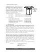
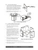
2. Specifications and Description The Hired Hand Chimney Vent is a natural ventilation accessory for mounting in the ceiling of animal confinement buildings or similar facilities. Air flow is adjustable by means of a movable baffle. The fully open position allows the entire vent area (see below) to provide vertical air flow from the inside to the outside of the building. An extension kit is available to provide an additional 4 foot of chamber length.
. Tools Required 3/8 in. (10 mm) Power screwdriver (portable) 5/16 in. (8 mm) Drive 7/16 in. (11 mm) Wrench 5/16 in. x 1-1/2 in. (8 mm x 38 mm) Lag Screws (provided) Tape Measure Carpenter’s Level Ladder Framing material for roof NOTE: Other Tools May Be Required According To Installation. 5. Assembling the Chimney Vent This section covers the steps necessary to assemble the Hired Hand 24” and 36” Chimney vent. Instruction for installing the vent into the building roof can be found in Section 6. 5.
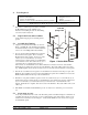
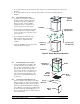
.4 1. 2. Attach Canopy Support Brackets Locate the four Canopy Support Brackets and install to the outside angle brackets of the assembled chamber as shown in Figure 3. Use (2) ¼ x 1 inch bolts, (2) ¼ inch washers and (2) ¼ inch lock nuts in each bracket. The Canopy Support Brackets also provide stability to the Chamber, so after they are installed, verify that the Baffle still rotates freely (if a Baffle was installed as in Section 5.2).
7. 8. 5.6 1. Do not tighten the top bolts in at this time. They will be removed when the Extension is added to the Chamber. Do not tighten the bottom bolts at this time. They will be removed later to install additional hardware. Canopy Support Brackets Attach Extension Brackets See Figure 5. Locate the four Extension Brackets. Bolt the extension brackets to the chamber using the predrilled holes. The upper bolts go into the Chamber.
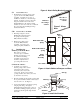
Figure 6 Attach Pulley Bracket Assembly 5.9 1. Attach Winter Door The Winter Door must be placed on the opposite side from the Pulley Bracket Assembly. See Figure 6. For ease of installation, slide the door from the hinge channel. See Figure 7. Then position the hinge and channel on the inside of the Chamber/Extension. Bolt using existing hardware at each corner of the door. Slide the Door into place after installing the hinge bracket and channel. 5.
6.2 Attach Flashing Side Mount Flashing See Figure 10. Attach the two Ridge Mount Flashing sections. Attach the two Side Mount Flashing sections. Additional caulking may be required depending on local requirements. Ridge Mount Flashing Figure 10 Install the Flashing 6.3 Attach Canopy to Chamber See Figure 11. Place the Canopy over the Support Brackets and align the Canopy evenly on the Support Brackets. For the 24 inch canopy, mark the location of the eight holes in the Support Brackets on the Canopy.
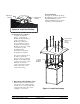
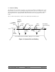
8. Actuator Cabling The following shows one example of a method to open and close the Chimney Vent Baffle and Door. The Linear actuator is connected to a rod running the length of the structure. The rod is connected to a spring which is in turn fastened to the end wall. When the linear actuator operates, the rod is pulled to the left in the example below hence opening the baffles. When the actuator reverses, the spring force closes the baffles.
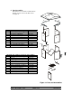
9. Parts/Assemblies Part Numbers and Assemblies available with the Chimney Vent are shown in the tables below. See Figure 12.
NOTES Part No. 4801-5369 Rev.
24" & 36" Chimney Vent