
Manual

Part No. 4801-5369 Rev. 10-07 Chimney Vent Page 4 of 12
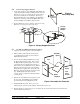
4. Tools Required
3/8 in. (10 mm) Power screwdriver (portable)
5/16 in. (8 mm) Drive
7/16 in. (11 mm) Wrench
5/16 in. x 1-1/2 in. (8 mm x 38 mm) Lag Screws (provided)
Tape Measure
Carpenter’s Level
Ladder
Framing material for roof
NOTE: Other Tools May Be Required According To Installation.
5. Assembling the Chimney Vent
This section covers the steps necessary to assemble
the Hired Hand 24” and 36” Chimney vent.
Instruction for installing the vent into the building
roof can be found in Section 6.
5.1 Unpack the Parts and Assemblies
Verify with the shipping invoice that all parts are
present.
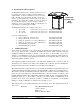
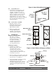
5.2 Assemble the Chamber
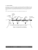
1. Align the four Side Panel Assemblies as shown in
Figure 1. NOTE: All of the Side Panel Assemblies
are identical, but they need to be identified (labeled)
now for ease of installing additional assemblies.
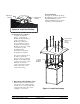
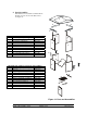
2. For ease when inserting the Baffle, first connect the
Front and Left sides together. Then connect the
Right and Rear panels together. For the 4 foot tall
vent use (4) ¼ x 1-3/4 inch bolts, (4) ¼ metal
washers and (4) ¼ inch lock nuts on each aluminum
corner channel. For the 10 foot tall vent use (8) ¼ x
1-3/4 inch bolts, (8) ¼ metal washers and (8) ¼
inch lock nuts on each aluminum corner channel. Place the lock nuts to the inside of the chamber.
Install, but do not tighten, the bottom screws in the Chamber. These bolts will be removed in a later
step. NOTE: Tighten other lock nuts securely, but do not distort the extruded channels or foam panels.
3. Slide the two assembled sections together. If a Vent Extension is not used, insert the pivot pins of the
Baffle into the predrilled pivot holes in the Left and Right side panels. If a Vent Extension is used, the
Baffle will be installed in a later step in the Vent Extension.
4. Bolt the two side panel assemblies together. For the 4 foot tall vent use (4) ¼ x 1-¾ inch bolts, (4) ¼
metal washers and (4) ¼ inch lock nuts on each aluminum corner channel. For the 10 foot tall vent use
(8) ¼ x 1-¾ inch bolts, (8) ¼ metal washers and (8) ¼ inch lock nuts on each aluminum corner
channel. Install, but do not tighten, the bottom screws in the Chamber. These bolts will be removed in
a later step.
5. If the Baffle was installed, install a Baffle stop bolt. See Section 5.3. Otherwise proceed to Section
5.4.
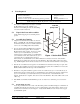
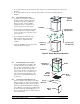
5.3 Install a Baffle Stop Bolt
Locate the predrilled hole in the center of the Front Side panels as identified in Figure 1. Drill the hole
completely through the panel. Insert a ¼ x 2-½" bolt through the center hole from the outside. Use ¼"
washers and ¼" lock nut as shown in Figure 2. Verify that the Baffle can rotate freely and is stopped
by the Baffle Stop Bolt.
Figure 1 Set the Side Panels
Baffle
Side
Panel
Assem.
Front
Rear
Right
Left
Baffle
Stop
Bolt
End with
Spring Cable