
Manual

Part No. 4801-5369 Rev. 10-07 Chimney Vent Page 6 of 12
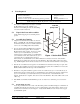
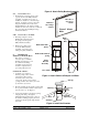
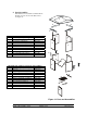
Figure 5 Attach Extension Brackets
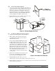
Chambe
r
Extension
Canopy
Support
Brackets
Extension
Adaptors
Upper 8 bolts
into Chamber
Lower 8 bolts
into Extension
7. Do not tighten the top bolts in at this time. They will be removed when the Extension is added to the
Chamber.
8. Do not tighten the bottom bolts at this time. They will be removed later to install additional
hardware.
5.6 Attach Extension Brackets
1. See Figure 5. Locate the four Extension
Brackets. Bolt the extension brackets to
the chamber using the predrilled holes.
The upper bolts go into the Chamber.
Attach with (8) ¼ x 1-½ inch bolts, (8)
washers and (8) and ¼ inch lock nuts.
2. Set the chamber on the Extension and bolt
the lower eight holes with the remaining
(8) ¼ x 1-½ inch bolts, (8) washers and (8)
¼ inch lock nuts.
3. Do not tighten the bottom bolts of the
Extension at this time. They will be
removed later to install additional
hardware.
4. Verify that the Baffle can rotate freely after
bolting the Extension together.
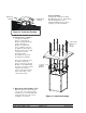
5.7 Attach Pulley Bracket Assembly
1. Locate the Pullet Bracket Assembly. This
assembly must be located parallel to the
axis of rotation of the Baffle. See Figure 6.
Bolt the pulley bracket assembly to the
bottom of the chamber (or the Extension if
used). Use the (2) ¼ x 1-¾ inch and (2) ¼
inch lock washers that were placed in the
bottom holes of the Chamber/Extension in
an earlier step.
5.8 Attach Wire Guard (Bird Screen)
Note the orientation of the flanges on the Wire
Guard. See Figure 6. They are perpendicular to
the Pulley Bracket Assembly. Recess the Wire
Guard inside the Chamber/Extension. Place the
Screen Brackets over the flanges and attach with
the bottom bolts in the Chamber/Extension. Use
(2)¼ x 1-¾ inch bolts and (2) ¼ inch lock nuts in
each Screen Bracket.
Chamber o
r
Extension
Baffle
Pulley
Bracket
Assembly
Bird
Screen
Winte
r
Doo
r
Screen
Brackets