
Manual

Part No. 4801-5369 Rev. 10-07 Chimney Vent Page 7 of 12
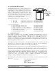
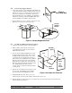
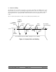
Figure 9 Install the Chamber
Framed
Opening
Chambe
r
Canopy
Roo
f
18 in (45.7 cm)
Flashing
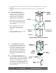
5.9 Attach Winter Door
1. The Winter Door must be placed on the
opposite side from the Pulley Bracket
Assembly. See Figure 6. For ease of
installation, slide the door from the hinge
channel. See Figure 7. Then position the
hinge and channel on the inside of the
Chamber/Extension. Bolt using existing
hardware at each corner of the door. Slide the
Door into place after installing the hinge
bracket and channel.
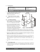
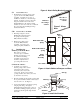
5.10 Attach Cables to the Baffle
1. Referring to Figure 8, run the
Baffle Cables with and without
the spring down through the
Pulley Bracket Assembly.
2. Run the Door cable up and
around the Pulley Bracket
Assembly. See Section 8 for
cabling and pulley installation.
6. Installing the
Chimney Vent in the Roof
This section covers the
necessary steps to install the
Chimney Vent into the roof of
the confinement building.
Assembly steps in Section 5
should be completed before
proceeding with Section 6.
6.1 Install the Chamber
1. See Figure 9. Construct a
framed opening in the roof that
is 26.5 inches (67.31 cm) by
26.5 inches (67.31 cm) for the
2 foot Vent. For the 3 foot Vent the
opening should be 38.5 inches (97.79 cm)
by 38.5 inches (97.79 cm).
2. Hoist the chamber up through the opening until
the top of the chamber extends 18 inches (45.7
cm) above the roof. See Figure 9.
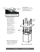
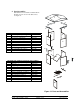
3. Connect the chamber to the framed opening
using lag bolts that go through the
aluminum angle brackets at the corners of
the chamber. Drill appropriate pilot holes
for the lag bolts through the angle bracket
and foam.
Figure 6 Attach Pulley Bracket Assembly
Figure 7 Winter
Door
Slide Door
out of hinge
channel
This side of
door faces
outside
Figure 8 Attach Cables to Damper and Door
Pulley
Bracket
Assembly
Door Cable
Baffle Cable with
spring
Baffle Cable without
spring
Doo
r
Baffle
Stop
Bolt