
Manual

Part No. 4801-5369 Rev. 10-07 Chimney Vent Page 8 of 12
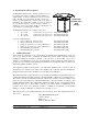
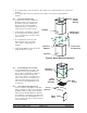
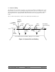
6.2 Attach Flashing
See Figure 10. Attach the two Ridge
Mount Flashing sections. Attach the two
Side Mount Flashing sections.
Additional caulking may be required
depending on local requirements.
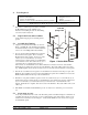
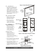
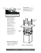
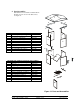
6.3 Attach Canopy to Chamber
See Figure 11. Place the
Canopy over the Support
Brackets and align the Canopy
evenly on the Support
Brackets. For the 24 inch
canopy, mark the location of
the eight holes in the Support
Brackets on the Canopy. Drill
a 3/8 inch hole for the
mounting hardware.
The 36 inch canopy has the
mounting holes predrilled.
Line up the mounting holes in
the Canopy and bolt the
Canopy to the Canopy Support
Brackets on the chamber using
(8) 5/16 x 1 inch bolts, (8) 5/16
whiz nuts and (8) fender
washers. The washers and the
heads of the bolts go on the
outside of the Canopy.
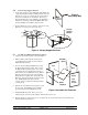
7. Operation of the Chimney Vent
The linear actuator should be adjusted
so the tension on the cable and spring
assembly uses no more than half of the
spring travel when the vent is closed
completely. See Section 8.
Figure 11 Install the Canopy
Figure 10 Install the Flashing
Side Mount
Flashing
Ridge Mount
Flashing
5/16" Fender
Washers on
top of
Canopy
Canopy
Support
Brackets