AM SELECT DISHWASHERS MODELS AM15 AM15F AM15T ML-130038 ML-130045 ML-130039 701 S. RIDGE AVENUE TROY, OHIO 45374-0001 937 332-3000 www.hobartcorp.com FORM 35320 Rev. B (Feb.
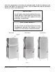
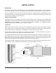
POST IN A PROMINENT LOCATION THE INSTRUCTIONS TO BE FOLLOWED IN THE EVENT THE SMELL OF GAS IS DETECTED. THIS INFORMATION CAN BE OBTAINED FROM THE LOCAL GAS SUPPLIER. IMPORTANT IN THE EVENT A GAS ODOR IS DETECTED, SHUT DOWN UNIT(S) AT MAIN SHUTOFF VALVE AND CONTACT THE LOCAL GAS COMPANY OR GAS SUPPLIER FOR SERVICE. FOR YOUR SAFETY DO NOT STORE OR USE GASOLINE OR OTHER FLAMMABLE VAPORS OR LIQUIDS IN THE VICINITY OF THIS OR ANY OTHER APPLIANCE. Model AM15 Model AM15F PRESSURE GAUGE Fig.
TABLE OF CONTENTS GENERAL 4 INSTALLATION 5 UNPACKING INSTALLATION CODES LOCATION CORNER INSTALLATION WATER REQUIREMENTS PLUMBING CONNECTIONS DRAIN CONNECTION WATER CONNECTION Without Electric Booster Water Heater With Electric Booster Water Heater GAS TANK HEAT (When Specified) VENTING REQUIREMENTS — WITH GAS TANK HEAT Rate of Exhaust Flow Calculations ELECTRICAL CONNECTIONS Dishwasher Without Electric Booster Check Rotation (Three Phase Machines Only) Dishwasher With Electric Booster (Separately Connec
Installation, Operation, and Care of AM SELECT DISHWASHERS SAVE THESE INSTRUCTIONS GENERAL Models AM15 and AM15T dishwashers can be configured for straight through or corner operation. Model AM15F is configured for front loading. AM15 and AM15T dishwashers are shipped from the factory in straight-through configuration. Straight-through machines can easily be converted to corner operation. Model AM15F includes a front-loader shelf and left- and right-side shields as standard equipment.
INSTALLATION UNPACKING Immediately after unpacking the dishwasher, check for possible shipping damage. If this machine is found to be damaged, save the packaging material and contact the carrier within 15 days of delivery. Prior to installation, test the electrical service to make sure it agrees with the specifications on the machine data plate; this includes the optional electric booster, if equipped. The dishwasher data plate is located at the bottom of the front panel.
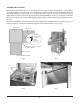
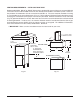
CORNER INSTALLATION Before placing the dishwasher in its operating location, check machine configuration. If the machine is being installed in a corner (Figs. 4, 5), clearances of 20 inches out from the dishwasher under the left-hand tabling by 27 inches above the finished floor and 15 inches out from the dishwasher at the right side by 27 inches above the finished floor must be provided for servicing.
A splash shield is available (at extra cost) for corner installations to cover the left side opening to the wall. Install the splash shield on the left side using the two 1/4-20 studs on the left rear corner with a lockwasher and nut for each (Fig. 8) and using the two 1/4-20 bolts, lockwashers and nuts on the left front corner (fasteners are provided in the kit).
PLUMBING CONNECTIONS WARNING: PLUMBING CONNECTIONS MUST COMPLY WITH APPLICABLE SANITARY, SAFETY AND PLUMBING CODES. DRAIN CONNECTION The drain connection is a 11/2" externally threaded pipe connected straight down from the bottom of the wash tank (Fig. 10). The connection can be made in any direction by using the proper fitting (not supplied) and routing to the appropriate drain line. If a grease trap is required by code, it should have a minimum flow capacity of 38 gallons per minute. DRAIN Fig.
GAS TANK HEAT (When Specified) Check the gas data plate attached to the dishwasher or the tag attached to the incoming gas piping for the type of gas to be used. GAS PRESSURE SPECIFICATION The burner is not adjustable. The maximum [FLOWING GAS PRESSURE — NOT STATIC] flowing inlet gas pressure must not exceed Type Inches W.C. (Water Column) FLOWING the Maximum value in the table.
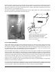
VENTING REQUIREMENTS — WITH GAS TANK HEAT Hobart model AM15, AM15F or AM15T dishwashers equipped for gas tank heat are not provided with a flue collar and are not intended to have the flue directly connected to a ventilation system. However, the products of combustion must be vented to the outside air. The most common method of venting is a vent hood over the entire dishwasher (Fig. 12). Refer to Rate of Exhaust Flow Calculations on the next page for calculations of the proper vent rate for your hood.
➤ LENGTH ➤ ➤ RATE OF EXHAUST FLOW CALCULATIONS ➤ CLEARANCE HEIGHT ➤ NOTE: Any listed and labeled factory-built commercial exhaust hood tested in accordance with UL Standard 710 by a nationally recognized testing laboratory, should be installed according to the terms of its listing and the manufacturer's installation instructions. Based on the 1996 International Mechanical Code. The Rate of air flow required for a vent hood is calculated using the following definitions (Fig.
ELECTRICAL CONNECTIONS WARNING: ELECTRICAL AND GROUNDING CONNECTIONS MUST COMPLY WITH THE APPLICABLE PORTIONS OF THE NATIONAL ELECTRICAL CODE AND/OR OTHER LOCAL ELECTRICAL CODES. WARNING: DISCONNECT THE ELECTRICAL POWER TO THE MACHINE (BOTH DISHWASHER AND BOOSTER IF APPLICABLE) AND FOLLOW LOCKOUT / TAGOUT PROCEDURES. Refer to the wiring diagram attached inside the front trim panel and to the machine data plate for service size requirements when connecting the dishwasher.
Dishwasher With Electric Booster (Separately Connected) Single phase machines with an electric booster require two separate connections, one for the booster and the other for the dishwasher (including motor, controls and tank heat). For single-phase machines, all power supply connections are made to terminal blocks (Fig. 16). The single phase dishwasher is connected to terminal block 1TB in the controls area. The single phase booster is connected to terminal block 2TB in the controls area.
DETERGENT, RINSE AID, SANITIZER DISPENSERS — TUBING INSTALLATION Detergent, rinse aid and / or sanitizer dispensers (not provided by Hobart) must have all connections sealed against leakage. The dishwasher uses 0.74 gallons of rinse water per rack at a flow rate of 4.4 gallons per minute at 20 psig flowing pressure (equivalent to a maximum head pressure of 46 feet of water). This information is used when setting the detergent, rinse aid or sanitizer pumps.
EQUIPMENT CONNECTIONS — Detergent, Rinse Aid, Sanitizer Dispensers WARNING: ELECTRICAL AND GROUNDING CONNECTIONS MUST COMPLY WITH THE APPLICABLE PORTIONS OF THE NATIONAL ELECTRICAL CODE AND/OR OTHER LOCAL ELECTRICAL CODES. WARNING: DISCONNECT THE ELECTRICAL POWER TO THE MACHINE (BOTH DISHWASHER AND BOOSTER IF APPLICABLE) AND FOLLOW LOCKOUT / TAGOUT PROCEDURES.
SETUP (All Models) Sanitizing Mode • With the machine OFF, press the ON key. • Immediately press and hold the OFF key. SET H °F °C C °F °C The display initializes until 88 displays. Next, SET X °F °C displays. X can be H, C or P: SET H = Hot Water Sanitizing, Internal Booster. C = Chemical Sanitizing, No Booster. P = Hot Water Sanitizing, External Booster. SET P °F °C • Press CYCLE to select P, H, or C as the sanitizing mode. After 5 seconds, the selection is saved and the machine turns off.
OPERATION PREPARATION The overflow tube must be in its proper location below the strainer pan (Fig. 23). Place the strainer pan and the strainer bucket in their proper positions (Fig. 24). STRAINER BUCKET OVERFLOW TUBE STRAINER PAN Fig. 24 Fig. 23 An automatic detergent dispenser is recommended. Closely follow supplier's instructions. Close the door; this will automatically close the drain. Open the manual gas valve (if applicable). Press the ON button to turn the power on (Fig. 25).
DISHWASHING Scrape the dishes to remove large particles of food and debris. Never use steel wool on ware to be loaded into the dishmachine. Fig. 26 Arrange the dishes in a rack. Do not stack dishes one on top of another, as water must have free access to all sides of every dish. Stand plates and dishes up edgewise in a peg-type rack (Fig. 26). Cups, glasses, and bowls should be inverted in an open-type or compartment type rack (Fig. 26).
CLEANING The machine must be thoroughly cleaned at the end of each working shift or at least daily. Never use steel wool to clean warewasher surfaces. Use only products formulated to be safe on stainless steel. 1. Push the OFF button. DRAIN LEVER 2. Open the machine door. 3. Clean off the dish tables into the dishwasher. 4. Drain the machine by lifting up the drain lever (Fig. 27). 5. Thoroughly cleanse and flush the dishwasher interior. Remove remaining soil with a soft cloth or brush and mild cleanser.
DELIME INSTRUCTIONS If the optional delime notification is activated and the DELIME light is on, follow the instructions, below. Delime is also necessary if deposits are visible inside or outside the machine. DELIME INSTRUCTIONS 1. Remove rack, drain tank, press "OFF". 2. Press and hold "CYCLE" & "ON" for 3 seconds; close door, unit fills then indicates "ADD DELIME". 3. Open door & add delime agent per supplier instructions for 14 gallon tank. 4. Close door, pump starts & display flashes "DELIME".
MAINTENANCE WARNING: DISCONNECT THE ELECTRICAL POWER TO THE MACHINE (BOTH DISHWASHER AND BOOSTER IF APPLICABLE) AND FOLLOW LOCKOUT / TAGOUT PROCEDURES. Wash Arms Upper and lower wash and rinse arms (Figs. 28, 29) should turn freely and continue turning for a few seconds after being whirled by hand. To check, DISCONNECT ELECTRICAL POWER SUPPLY (BOTH DISHWASHER AND BOOSTER IF APPLICABLE), rotate arms and remove any obstructions causing improper operation.
TROUBLESHOOTING Manual Reset Button on Pump Motor If the pump motor becomes overheated, the thermal overload protector will cause the motor to not operate. If this occurs, contact Service. To avoid a service call, check symptoms and related possible causes. If machine still does not operate properly, contact Service. SYMPTOM No machine operation. Dishes not clean. Spotting silverware, glasses and dishes. POSSIBLE CAUSE 1. Machine off, turn machine on. 2.
SYMPTOM POSSIBLE CAUSE Inadequate rinse or rinse 1. Dirty line strainer causing reduced water flow. Turn off water supply, remove water temperature too low. strainer cap, withdraw and clean screen. Reassemble. Possible EE display. 2. Low supply line pressure. 3. Excessive mineral deposits throughout wash and rinse system. Deliming may be necessary, refer to page 20. 4. Incoming water temperature to booster (if applicable) below 110°F.
SERVICE Contact your local Hobart-authorized service office for any repairs or adjustments needed on this equipment. If a gas orifice fitting is to be replaced, have it serviced by qualified Hobart-authorized service personnel. Long-term service contracts are available on this and other Hobart products. Call 1-888-4HOBART for Hobart Service 24 hours a day. FORM 35320 Rev. B (Feb. 2005) – 24 – PRINTED IN U.S.A.