Dear Camper Owners, We would like to congratulate you on the purchase of your new HOBBY camper and hope that you will always enjoy traveling with it. Please read this manual carefully, even if you have been driving a camper for a longer period of time. It will help you to avoid operating errors and damage to the vehicle and its equipment. Correct handling of all technical details will increase your driving comfort and maintain the value of your camper.
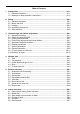
Table of Contents 1 Introduction...............................................................................................................01-1 1.1 General information............................................................................................01-1 1.2 Markings in these operation instructions............................................................01-2 2 Safety.........................................................................................................................
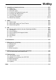
7 Installation of electrical devices.............................................................................07-1 7.1 Safety tips...........................................................................................................07-1 7.2 Service panel......................................................................................................07-2 7.3 Electrical supply..................................................................................................07-4 7.
1. Introduction Our campers are continuously being further developed. Please understand that we reserve the right to make changes to their equipment, shape and technology. Therefore, HOBBY shall not be liable for any claims arising from the contents of this handbook. The equipment used at the time of printing is described in this handbook and should be transferred accordingly to the layouts of all the different camper variations. Please understand that we cannot describe all of the individual variations.
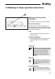
1.2 Markings in these operation instructions 1 Markings in these operation instructions The handbook explains the camper as follows: Texts and illustrations The texts which accompany illustrations are found directly to the right of the illustrations. Details in illustrations (here: entry door) are marked with position numbers (1). Lists - Lists are based on key points and are preceded by a dash.
2. Safety 2.1 General information Keys The following keys are provided with the camper: - Two keys which fit into the following locks: - entry door, - service flaps, - toilet flap. - gas-bottle container lid - fresh-water tank lid Warnings and information labels are attached both inside and outside the vehicle. These are meant for your safety and may not be removed.
Fighting a fire • Evacuate all passengers immediately. • Close the main shut-off valve on the gas 2.2 Before the drive bottle as well as the shut-off valves on gaspowered appliances. • Shut off the electrical supply • Sound alarm and call the fire department. • Only fight the fire yourself if this is possible without risk. As the owner and driver, you are responsible for the condition of your vehicle.
ward as far as possible or fold over the satellite dish. • If necessary, secure the roof load and lash it to prevent slippage. • If necessary, secure all bicycles and lash them to prevent slippage, ensuring that they do not cover any lighting equipment. • In winter, the roof must be free of snow and ice before you begin to drive. Post a list with all significant weights and measurements of the carriage in a highly visible place in the base vehicle.
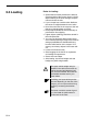
2.3 Loading Rules for loading: • Spread the load evenly between the left and • • • • • • • • • 02- right-hand side of the camper. Heavy or bulky objects belong in the lower storage compartments and near the axle. If your camper has a tandem axle: distribute the centre of weight between the two axles. Never focus the load in the camper to the rear (danger of swinging back and forth). Heavy objects should be stowed securely to prevent them from slipping.
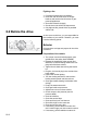
Stowage areas in the camper 1 2 3 - Light objects (1) such as towels and lightweight laundry. - Medium-weight objects (2) such as clothing, laundry and food. - Heavy objects (3) such as the outer tent, boat motor or crates of drinks. If your camper is equipped with a rear bicycle rack, the reduction in the drawbar load created by the bicycles must be compensated by the rest of the load.
2.4 Handling Performance Driving Take a test drive or a safety training course before the first long drive to better acquaint yourself with the carriage in driving conditions. Rules for driving • Do not underestimate the length of the • • • • • • • • carriage. Exercise special caution when driving toward yards and through gates. In conditions with strong side winds, slick ice or wet roads, the carriage could move back and forth. Adjust driving speed to overall street and traffic conditions.
Brakes A trailer carriage behaves differently from an individual vehicle while braking. Therefore, it is advis-able (especially for inexperienced drivers) to conduct several braking tests on a suitable surface. The braking distance for a carriage is longer than that of an individual vehicle. The load in the caravan also has a significant influence on the braking distance. Rules for braking • Note the longer braking distance on wet roads.
When positioning the camper manually, only use the steering handles at the front and rear ends of the camper. Never push on the plastic parts or the walls. 2.5 After the drive Choosing a parking place Rules for choosing a parking place: • The parking place should be as horizontal as possible. • Check to see that the entry step is positioned horizontally (important for refrigerator func tion). • Balance the lengthwise slant with the front landing wheel.
Water installation Water left standing in the fresh water tank or the pipes quickly becomes undrinkable. Therefore, check the water pipes and the freshwater tank after each use to ensure they are clean. If necessary, use chemical or biological disinfectants and rinse well with sufficient fresh water.
02-10
3. Undercarriage and vehicle registration 3.1 General information Frame parts and axles are components of the undercarriage. No technical modifications are allowed; otherwise, the terms of operation are no longer valid! For the sake of traffic safety, the vehicle undercarriage must be maintained just as conscientiously as the base vehicle itself. This maintenance should be carried out by your HOBBY dealer. If spare parts are required, use only the original parts designated by the manufacturer.
The camper's turning rod spring axle unit is equipped with compact wheel bearings. The cylinder hub, compact bearings and axle nuts form a closed unit. The compact bearings are free of maintenance due to their special grease. The wheel brake may never be repositioned on the fixing lock or on the yoke end of the bars! Only reposition the wheel brake on the self-securing stationary hexagonal nut! You can find further guidelines in the operating instructions from the axle supplier.
3.2 Safety coupling WS 3000 The camper is equipped with an anti-rolling coupling in accordance with ISO 11555-1. This safety coupling stabilises the camper while driving and ensures better driving performance. Please note the additional operating instructions and the manufacturer's safety instructions. WARNING: The laws of physics cannot be defied with a safety hitch.
Activation of the stabilization system 1 • To activate the stabilization system, the 2 3 operation lever must be moved downward out of the closed position (2) until it locks in (3). The spring corpus will become tense in the process, so that contact pressure is created on the coupling ball via the friction elements. Afterward, the operation lever lies approxi- mately parallel to the drawbar axle.
Maintenance Coupling ball on base vehicle Ensure that the coupling ball meets the required dimensions and is undamaged, clean and free of grease. When using dacromet-coated (dull silver anti-corrosion coating) as well as lacquered coupling balls, the coating must be removed completely with sandpaper (200-240 grain) so that it does not create deposits on the friction lining. The metal surface of the coupling ball must be bright.
Noises Certain noises can occur during the course of the drive; these noises, however, have no influence on the operative effectiveness of the tension ball coupler. Possible causes of these noises can be: 1. a dacromet-coated coupling ball on the base vehicle, 2. a galvanized coupling ball on the base vehicle, 3. a damaged or dirty coupling ball on the base vehicle, 4. dirty friction elements on the tension ball coupler. 5.
3.3 Locking brake facilities The components of the brake facilities, particularly the overrunning equipment, wheel brakes and towbar were checked in accordance with the appropriate EU Guidelines and may only be used in a licensed combination. If you alter or modify any components of the brake facilities, the operation permission loses its validity. Modifications may only be made with the manufacturer's permission.
sign of strong brake lining wear is described in the aforementioned check for the overrunning equipment: if the safety clutch can be pushed in more than approx. 5 mm. In this case, the wheel brakes must be regulated by an experienced shop or, if necessary, the brake shoes must be renewed. • When driving downhill on a mountain pass, check to ensure that the brakes are cooled sufficiently. • Put the base vehicle into a lower gear and drive downhill at slow speed.
The crank for the rotating stanchions is located at the front in the gas-bottle container. It is attached firmly to the bottom of the container. 3.7 Vehicle registration Every vehicle which uses public roads is subject to registration. This includes your new camper. You can register the camper at your local registration office.
Name plate Permit number Vehicle ID number (FIN) Permissible maximum weight Permissible axle load, 1st axle Permissible axle load, 2nd axle 03-10
3.9 Fit for a Speed of 100 km/h 1. Your HOBBY camper is technically equipped for a maximum speed of 100 km/h. Under no circumstances may this speed be exceeded! 2. Note the permissible maximum speeds for trailer carriages in the country in which you are travelling! 3. Road traffic regulations in Germany were changed on 22 October 2005. Your camper was already set to a speed of 100 at the factory, and this has been entered in the camper's registration documents.
3.10 Definition of mass Definition of masses (weights) for campers The EU regulation 97/27/EG applies for calculating the masses (weights) and for the loading which results from these calculations. The EU regulations correspnd to a great extent to the norm DIN EN 1645-2. The terms and basic calculation elements used in this description are explained in the following: 1. Gross vehicle weight rating (g.v.w.r.) The indication of the gross vehicle weight rating is taken directly from the HOBBY factory.
If you are not sure whether you have overloaded the vehicle, weigh your vehicle on a public vehicle scale. Overloading can lead to malfunction or even tire blowout! This presents the danger of the vehicle spinning out of control, which endangers you as well as other dri- vers and pedestrians.
03-14
4. Wheels, tires Only use those tires designated in the registration documents. Other tire sizes may only be used with the permission of the manufacturer (ABE). • Check tires regularly to ensure that the tread is worn down evenly; check tread depth; check for external damages. • Always use the same make and model of tires (summer or winter tires). • Drive carefully on new tires for a stretch of approx. 100 km to enable them to develop a full road grip. 4.
If the tire pressure is too low, the tire can overheat. This can result in serious damage. 4.3 Profile depth and age of tires The correct tire pressure is given in the table on wheels/tire pressure found under "Technical Information" or on the labels in the gas-bottle container and on the wheel cover. New tires are needed (at the latest) when the profile depth measures 1.6 mm. Tires age even when used rarely or not at all.
4.4 Rims Only use rims that are covered by the vehicle licence. Should you wish to use other rims, please note the following: Rules for the use of other rims: - Size, mechanisms, compression depth and the load/bearing capacity must be sufficient for the permissible total mass. - The chuck cone of the fastening screw must correspond to the rim mechanisms. Modifications can only be made with the manufacturer's permission.
4.5 Changing the tire Preparing to change the tire • If possible, only change the tire when the • • • 1 • • base vehicle is coupled to the camper. Park the trailer carriage on as firm and even a surface as possible. If you have tire trouble on a public road, turn on your hazard warning signal lights and set up the warning triangle. Base vehicle: Pull the handbrake, set the wheels straight, put the vehicle in gear or, if you are driving an automatic, set the gear to P.
Warnings for changing the tire: Only use the specifically designated jack for the corresponding frame parts. For example, on the axle pipe corresponding to the swinging lever group or on the stringer in the area of the axle fasteners. Damage or even an accident resulting from the vehicle's toppling over can occur if the jack is applied to other parts of the vehicle. The jack is only to be used for changing tires.
• Lower the jack and remove it. • Tighten the wheel fatening screws evenly with the wheel wrench. The nominal value of the attachment torque is 110 nm for steel rims and 120 nm for aluminium rims. • Release the handbrake and reactivate the stabilization system. You should have a functional spare tire available at all times. Therefore, have the spare tire replaced without delay. Tire repair kit Do not use the tire repair kit if the tire was damaged as a result of driving without air.
D Hold the bottle down with the filling tube and then press them together. Press the entire bottle contents into the tire. Pull the fill hose off (1) and screw the valve insert (2) tightly into the tire valve with the valve-core remover (3). E Open the air hose (5) on the tire valve. Insert the plug (6) into the cigar lighter socket. Then pump the tires (Fig. 7).
04-
5. Exterior structure 5.1 Ventilation and De-aerating Rules for forced ventilation 1 Proper ventilation and de-aerating of the vehicle is a prerequisite for ideal living comfort. A draftfree forced-ventilation system is located in the floor and a forced de-aerating system is located in the ceiling which should not be interfered with. We recommend that you open the roof bonnets whenever you live in the camper. 2 Cooking, wet clothing, etc., produces vapor. Every person loses up to 35 g of water per hour.
Refrigerator 2 The ventilation bars provide the refrigerator with fresh air from outside to ensure sufficient cooling performance. The ventilation bar is located at the bottom of the exterior vehicle wall. The de-aeration bar is located above the ventilation bar. 1 there is a danger of suffocation if ventilation openings are blocked! Therefore, do not block ventilation openings.
5.2 Vehicle keys External entry door To open: • Unlatch the lock with the key. • Pull the door handle. • Open the door. To close: • Shut the door. • Turn the key until the latch clicks audibly. • Turn the key back into the vertical position and pull it out. External Door lock model a To avoid damage, do not use the track for the insect screen as assistance when entering the camper. The entry door is your escape route in an emergency.
Model b: B To open: A • Reach into the grip plate (A), pull the release lever, open the door and let go of the lever. To close: • Pull the door shut. • Press the locking button (B). Entry door model b 4 Stable entry door The upper (3) and lower (2) parts of the entry door can be opened and closed separately by opening the door and then unlocking the upper part (3) of the door from the lower part.
Never lock the upper part of the door when the insect screen is closed. The insect screen must always be open when you lock the door. Locking the upper part of the door Model a: • Push the bolt (4) outward. • Connect the upper part of the door (3) to the lower part (2). • Push the bolt (4) inward or let it snap back and securely fasten both parts together. Model b: • Turn the lever (4) to a horizontal position in order to securely connect the upper and lower parts of the door.
All of the fastenings on the service flap must lock into place when closing to ensure that the flap will always be closed tight. If the flap is not closed correctly, it could become permanently deformed, especially when the camper stands unused for a longer period of time. Spray the sealing gaskets of the service flaps regularly with silicon to ensure that they will always move easily and operate reliably. 5.4 Gas-bottle container flap To open: • Unlatch the lock (1) with the key.
5.6 Roof and roof rail Rules for loading the roof rail: • Fasten the carrier or the cross braces for the roof loads to the roof rail. • Only store light baggage on the roof. • Lash the roof load sufficiently and secure it against slippage or falling. • Do not load the roof excessively! The heavier the roof load, the worse the overall handling of the vehicle. The maximum permissible load for the roof rail is 50 kg. Note the maximum permissible axle burdens.
5.7 Guide rail for outer tent The guide rail for the outer tent, which is used to insert the weather strip, is beaded at the rear of the camper on a level with the taillights as well as at the lower edge of the front end of the camper. The filling ribbon of the guide rail for the outer tent deliberately hangs several centimetres out of the guide rail to ensure the rainwater and moisture will drip off. Never cut off the extra bit of filling ribbon that hangs out. 5.
6 Interior structure 6.1 Opening and closing doors and flaps Stowage cupboards To open: • Pull the handle until the flap opens. To close: • Press the flap on the handle until you feel the flap shut. Furniture doors with handle Washroom door • Push the handle to open and shut the door. Furniture doors with knob Wardrobe • Turn the knob to open and shut the door.
Furniture doors with sliding handle Kitchen cupboards (except Excelsior) 1 To open: • Using your thumb and index finger, push the sliding handle (1) up. • Pull on the handle until the cupboard door swings open to the side. To close: • Using your thumb and index finger, push the sliding handle (1) up. • Using the handle, push the cupboard door closed. • To fasten the door, let the sliding handle (1) snap back in its original position.
6.2 Media oval (rotating TV/bar) The media oval is a room divider, mounted on a pivot, which can be used as both a bar and a TV cupboard for flat screens. To swing the media oval, pull the catch (1) and, after swinging out the media oval, press and snap the catch back into place to secure the media oval. The switch (2) for turning the LED lighting for the bar on and off is located directly beneath the media oval next to the 230 V sockets for the kitchen.
6.3 Seat chests and conversion of beds The seat groups can be converted into comfortable beds. Elevating table model Conversion: • Remove the seat and back cushions. • Pull the latch of the table frame upward and release. • Pull the latch of the table frame towards the interior of the vehicle and lower the table. • Replace the seat cushions and pull themto the middle of the table. • Fill the empty spaces with the back cushions.
Bed expansion for vehicles with rear seat group Setting up the beds left backrest Rear crosswise seat right seat right backrest left seat 6.4 Children's beds • Windows by the children's beds are secured against accidental opening, to effectively pre vent children from falling out. Be careful when using the upper bed for small children, as there is a danger that they may fall out. Never leave small children unattended in the caravan.
6.5 Windows Hinged windows To open: The window can be adjusted to open at varying degrees: • Turn the latch into the vertical position. • Press the window outward until you hear a click. The window automatically remains in this position. Windows by the children's beds are secured against accidental opening, to effectively prevent children from falling out. To close: • Lift the window slightly outward so that the hinge disengages. • Close the window.
To shut the insect screen: • Pull the insect screen (3) completely down with the strap (4) and let go. The screen re mains in this position. To open the insect screen: • Pull the insect screen (3) slightly down with the strap (4) and then guide it upward. The screen rolls upward automatically. Do not let the shade or the insect screen fly upward! To avoid consequential damage, leave the shades and pleatings open when the caravan is not in use. 6.
During this season and depending on the model and version, two different types of roof bonnets will be installed. Please look at the photos opposite this text to decide which type has been installed in your camper and note the corresponding operating instructions. To open the roof bonnet: Before opening the roof bonnet, ensure that there is nothing above the bonnet, e.g. branches. The bonnet can be opened to an angle of 60°.
Shade The shade is infinitely variable; simply pull the handle to the desired position or until the lock snaps into the handle of the insect screen. Opening/closing the insect screen Push the handle strip of the insect screen against the handle strip of the pleating until the lock snaps into the handle strips. Round roof bonnet 1 To open: • Pull the lower end of all three locking mechanisms (1) towards the middle of the window and release them.
06-10
7. Installation of electrical devices 7.1 Safety tips The installation of electrical devices in the HOBBY camper have been carried out in accordance with the valid regulations and norms. Please note: • Do not remove safety tips and warnings on the electrical equipment. • The installation spaces for electrical equipment such as distribution fuse boards, electric power supply, etc., may not be used as additional storage spaces.
7.2 Service panel 2 1 3 4 11 5 6 7 8 9 10 Push-button Function 1 Heating system 2 Floor heating (not standard equipment) 3 Light in outer tent 4 Wall lamps 5 Kitchen lamp 6 Diffused reflecting lights 7 Ceiling lamp 8 Indirect lighting 9 Indirect lighting 2 10 Water tank 11 Main switch On/off switch - red LED shows function. On/off switch - red LED shows function. General note 07- On/off switch for light in outer tent.
Secondary panel 1 Sleeping area Push-button Function Left Centre Right On/off switch for mounted spotlight on left side of bed. Holding the push-button activates the dimmer function. Light increases and decreases. On/off switch for ceiling lamp over suite. Holding the push-button activates the dimmer function. Light increases and decreases. On/off switch for mounted spotlight on right side of bed. Holding the push-button activates the dimmer function.
7.3 Electrical supply Electricity for the camper can be obtained from the following connections: - 230 V mains connection 50 Hz. (1) - via the base vehicle if it is connected using the 13-pole plug (limited functions) - via a built-in auxiliary battery (not included). Everything that uses 12 V, such as lighting, water supply, etc., is available. Supply via mains connection The camper receives its electric power supply via the 230 V CEE feeder plug on the side wall of the vehicle.
Rules for the mains connection: • Use only a 3 x 2.5 mm2 cable with a maximum length of 25 m, a CEE plug and connector to connect the camper to an external 230 V mains. If the mains operates via a cable drum, this must be completely unwound, as otherwise induction may cause the cable to heat up and burn. • If a residual current operated device (special installations) has been installed in your camper, it must be checked regularly by activating the test button.
7.4 Function of the electrical supply unit The redirect from battery operation to the mains connection occurs automatically as soon as a mains connection is available. The electrical supply unit converts the external network voltage for those 12 volt devices present with a converter. All of the lamps in the camper are run on 12 V direct current. Only the large electrical devices, such as the therme, microwave, air conditioning, etc., are 230 V devices.
7.5 Changing the taillight bulbs Carefully remove the protective caps with a screwdriver. Remove the four fastening screws with a crosstip screwdriver. Now you can remove the taillight from the frame. Remove the holder by loosening the screw. The bulbs are now freely accessible. Put the taillight back together by repeating the process in reverse.
07- w ei ß g rü n b ra u n 3 4 5 6 b l au blau / weiß weiß / rot violet t w e i ß / bl au 9 10 11 12 13 6 red 1,5 2,5 Electric power supply (steady plus) Reverse light Left taillight, clearance light, running light and number plate light white M as s e/ red für 9 violet Vit/blå 211 ,5 12 13 2,5 1,5 2,5 Mass for 9 Trailer number plate, mass from 3 Mass for 10 supply, ignition-controlled A nhängererk ennu2,5 ng M asElectric s e von power 3 blue / white 110 ,5 blue M a
"Jäger" outlet (13-poled) View from connection side Contact 1 2 3 4 5 6 7 9 10 11 12 13 Circuit direction indicator, left fog lamp mass (for circuits 1 through 8) direction indicator, right right taillight, silhouette light, limitation lamp, and license-plate illumination brake lights left taillight, silhouette light, limitation lamp, and license-plate illumination electrical supply (constant positive) electrical supply, ignition switch controlled mass for circuit 10 mass for trailer recogn
7.7 Lighting in the camper can be switched via the control panel Surrounding LED spotlights (1) in the lounge area (Excelsior: Halogen spotlights) 1 Corner shelf with integrated lamp can be switched on/off separately.
Indirect lighting (5) above the windows by the round seating arrangement 5 Dimmable ceiling lights above the seating arrangement (depending on the model) The control panel is used to switch the kitchen light on and off. The wardrobe lighting is activated via an integrated contact switch by opening the wardrobe doors (cannot be operated using the control panel). The LED lighting is battery-operated. Before using this for the first time, you must pull off the foil that protects the battery contacts.
Turn the nose of the bear on the children’s bedside light to switch it on and off. This lamp can be dimmed and set to operate as a night-light (“blue ears”) (cannot be operated using the control panel). The night-light can be switched on and off separately using the switch underneath the children’s bedside light. The light in the outer tent is switched on and off using the control panel. When in use in public traffic, the light in the outer tent must be switched off. 7.
8. Water 8.1 Water supply The entire water system in your caravan has been manufactured from food-safe materials. Despite this, we recommend that you do not use this water for drinking. General information • Water that is suitable for drinking should always be used with working with food. This also applies to washing your hands and cleaning the objects that have come into contact with food.
Rolling 22 l fresh water tank with service flap The fresh water tank can be rolled or carried. To add water: • Open the service flap. • Remove the screw connector and pull the immersion pump from the fresh water tank. • Pull out the canister. • Add drinking water to the tank. • Close the tank with the lid when transporting. To remove water: • Turn the faucets to "cold" or "hot". The pump switches on automatically when operated via electricity. To empty the tank: • Open the service flap.
50 l fixed tank from 540 series onwards The tank has a volume of 50 liters. 1 3 The tank is filled with fresh water by means of the filler neck (2) on the side wall. The fresh water filler neck is identified by a blue screw cap as well as a water faucet symbol on the lower edge of the frame. The screw cap is opened and closed by means of the enclosed key for exterior flap locks and the door of the structure.
2 To remove water: • The water will be mixed to the desired temperature according to the position of the pre-mixing unit. 3 Emptying the therme: • Switch off the electricity for the water pump 4 1 Plan for warm water supply • • • • • by pressing the control panel (3) of the main switch for 5 seconds. Open all faucets. Set all pre-mixing valves to "warm" if necessary. Open the runoff valve (4). Check to see if water runs out. Close the runoff valve (4) after emptying (if necessary, blow the line out).
8.3 Water flushing toilet 1 Toilets with fixed seat and fresh water tank To prepare the toilet 1. Open the service flap on the exterior wall of your camper. MAX 2 2. Swing the fill stanchions of the faeces tank in a 90° arch and remove the water tank extension (located under the handle closest to the drain nozzle). 3 3. Turn the water funnel outwards, remove the cap and place the extension over the funnel. Pour the required amount of Thetford toilet additive into the water tank.
5 4 6 5. Remove the extension and return it to its original position on the faeces tank. Depending on the amount of space between the door and the faeces tank, you can also use a peg to fasten the extension to the door. Screw the cap back onto the water funnel and press it back inside towards the fresh water tank. 150 ml of water are left in the water funnel when the water tank is empty. 6. Remove the faeces tank by pulling the holder clamp up. 7 7. Pull the faeces tank outward until it clicks.
10 10. Push the faeces tank through the door back to its original position. Do not use force the faeces tank back in; this could lead to severe damage. 11 11. Use the securing clamp to ensure that the faeces tank is locked into place and close the service flap. Operation 12. Let some water run into the toilet-bowl by pressing briefly on the flush knob or open the valve by turning the lever counterclockwise. Your Thetford toilet is now ready for use. 12 13 13.
14 14. Ensure that the valve is closed. Open the service flap on the outside of the camper. Pull the holder clamp up and remove the faeces tank. 15. Remove the water tank extension first to prevent its being lost when emptying the faeces tank. 16. Place the faeces tank in a vertical position (tiltable lever on the top, wheels on the bottom). Press the lever down and move it away from the faeces tank so that the tank jumps out of its locked position. 15 17.
19 18 19. If necessary, prepare the toilet once again for use. Replace the water tank extension in its original position on the faeces tank. Push the faeces tank back into the toilet and close the service flap. Storage If you do not plan to use your Thetford toilet for a longer period of time, it is important that you follow these instructions first: 20 22 Drain the water from your camper's central water system. 20. Open the valve by turning the lever on the toilet counterclockwise.
08-10
9. Gas 9.1 General safety rules for the use of liquid gas facilities The gas operation pressure is 30 mbar. Inspection of the gas facilities • Hae the gas facilities checked by an expert before the first use. • The gas facilities should be inspected by an expert every two years. This inspection should be documented on the inspection certificate in accordance with the German Association of Gas and Water Experts, worksheet G 607, and EN 1949.
• Pressure regulators must have a fixed output pressure of 30 mbar. The requirements of EN 12864, Appendix D, apply accordingly. The regulator must have a rate of flow of 1.2 kg/h. • Connect the regulator knobs very carefully by hand. do not use keys, pliers or similar tools. • Use the de-icing system (Eis-Ex) for the regulator knobs when the temperature drops below 5° C. Before first use • Ventilation openings should remain unobstructed. • If necessary, remove snow from the flue.
9.2 Gas supply The camper is equipped with propane gas facilities. These facilities opeate the following devices: - cooker - refrigerator - heating element - warm water boiler, if necessary - special equipment, if necessary - baking oven, if necessary Bottle container 3 2 The gas-bottle container holds two 11 kg bottles of propane gas (1). The gas bottles are connected to the supply line by a safety regulator hose (2).
Changing gas bottles: Never smoke or light open fires when changing gas bottles. After changing bottles, check whether gas is escaping from the points of attachment by spraying these with a leak indicator. • Open the flap of the gas-bottle container. • Shut the main shutoff valve on the gas bottle. • Manually unscrew the gas pressure regulator • • • • • and gas hose from the gas bottle (left-handed thread). Loosen the belts and remove the gas bottle. Put full gas bottle back in the bottle container.
9.3 Hot-air heating Heating element S 5002 and S 3002 Heating while driving is forbidden. - S 5002 model 560 to 750 - S 3002 model 400 to 540 (except 460 LU Excellent) Place of installation: - in the closet or the corner of the flue Before first use: • Several air outlet nozzles have been built into the camper. Pipes lead the hot air to the air outlet nozzles. Turn the nozzles so that the hot air is expelled where you want it. • Check whether the flue is unobstructed. Any covers must always be removed.
• If the flame extinguishes again, re-ignition 1 takes place during the closing phase of the fusible cut-out of the ignition safety switch (approx. 30 seconds). • If no flame is ignited, the automatic ignitor (2) will continue to work until the operation handle (1) is switched to “0”. To shut off: • Turn the operation handle (1) to position "0". The automatic ignitor is thereby shut off. • Close the bottle valve and the quick-close valve if the unit is not used for a longer period of time.
Circulation fan 1 The heater in your camper is equipped with a circulation fan. It circulates the hot air throughout the interior of the camper. Use the knob to set the desired heating capacity. This knob (1) is located in the radiator cover (Fig. 1 and 2). Adjustment by hand: • Set the switch to position (1) (Fig. 3). • Adjust the desired level via the turning knob (4). To turn off: • Set switch to position (2). Fig. 1 Automatic operation: • Set switch to position (3).
9.4 Hot-air heating with integrated boiler (only in 460 LU Excellent) Heating while driving is forbidden. The Combi 4 LPG heating is a hot-air heating system with an integrated hot-water boiler (contents: 10 l). It is possible to operate the heating system both with and without water. Location • In the left single bed behind the washroom. Initial operation • Set the air exit nozzle in the camper so that the hot air exits where you want it to. • Check that the flue is unobstructed.
Frost control “FrostControl” is a safety or drain valve that does not operate on electricity. If there is danger of frost, it automatically empties the contents of the boiler using a draining stanchion. If there is excess pressure in the system, the pressure is automatically equalised intermittently by means of the safety valve.
• Heating without controlled water temperature: Turn the switch to operative setting (d). Turn the knob (a) to the desired setting for the thermostat (1-5). The green LED (b) for operation will shine; at the same time, it shows the setting for the room temperature you have selected. The yellow LED (g - warm-up phase for the water) shines only as long as the water temperature is below 5° C. The device automatically selects the required power setting.
Filling the boiler • Close the drain valve by pressing on the button until it locks in place. • Turn on the 12 V power supply by means of the main switch on the control panel. • Open all of the faucets and set them to “hot”. Leave them open until the boiler has been filled by displacement of the air. If the temperature is below approx. 7° C, turn the heating on first to heat up the installation space and the FrostControl on the drain valve.
Important information • Please read the separate operating instructions carefully before initial operation of the heating system. • Always turn off the main switch for the heating system whenever the vehicle is not in use. • If there is danger of frost, always drain off the fresh water in the hot-water heater. • You may not start the heating if the device has not been filled with glycol.
9.5 Refrigerator Your camper is installed with a refrigerator made by Dometic or Thetford. If the external temperature is high, full refrigerating capacity can only be ensured by means of sufficient ventilation. If necessary, to achieve better ventilation, the refrigerator’s ventilation grille can be removed at the campsite. Please follow the separate operating instructions provided by the manufacturer. Methods of operation The refrigerator can be operated in three different ways.
Gas operation • Set the energy selection switch to gas operation. • Open the main shutoff valve on the gas bottle and the gas shutoff spigot marked “refrigerator”. • Turn the thermostat up full and keep it pressed down. The refrigerator will either ignite automatically or by using the knob for manual ignition (depending on your model). • When it is ignited, let go of the thermostat. Repeat the previous step if it has not ignited. • Use the thermostat to regulate the cooling efficiency.
9.6 Gas cooker The kitchen segment of the camper is equipped with a 3-flame gas cooker. Before first use: • Open the bottle valve and the quick-close valve in the gas line. • The roof ventilation or the window must be open while operating the gas cooker. • Operation handles, which must be pressed to ignite gas devices, must automatically spring back into the original position upon release.
Use potholders or mitts when handling hot pots, pans and similar objects. Danger of injury! Keep the cover (1) open after cooking for as long as the burners are still giving off heat. Do not store easily inflammable objects such as dish towels, napkins, etc., near the cooker. use the protective device on the cooker at all times when cooking. Danger of fire! 9.7 Oven • The ventilation openings on the oven must never be closed.
Turning on the oven: • Switch on the 12 V power supply using the main switch on the control panel. • Open the main shutoff valve on the gas bottle and the gas shutoff spigot marked “oven”. • Open the oven door completely. • Position the baking tray or grill so that it is not in direct contact with the flame. • Press the switch lightly and set it to the desired ignition position (oven or grill, if available). • Press the switch. Gas flows to the burner and the flame will ignite automatically.
09-18
10. Accessories Note the detailed operation instructions, installation instructions and circuit diagrams from the manufacturers when using accessories. These are located in your service package. • • • Any changes to the status of the camper as delivered by the manufacturer may endanger driving performance and roadworthiness. Any accessories, add-ons, modifications or mounted parts that have not been approved by HOBBY may cause damage to the vehicle and impair its roadworthiness.
10-
11. Maintenance and upkeep 11.1 Maintenance Maintenance intervals fixed maintenance intervals apply to the camper and the devices installed in it. Rules for maintenance intervals • • • Have the first maintenance performed by a HOBBY dealer 12 months after the initial registration. Havve all further maintenance performed once annually at a HOBBY dealer. Have all maintenance on built-in devices performed in accordance with the corres ponding maintenance intervals indicated in the operating instructions.
Rules for greasing and oiling: • Have the swinging lever bearings greased after every 2,000 to 3,000 kilometers driven. • Grease the bearing spaces on the casing of the overrunning system. • Oil movable parts such as bolts and joints. • Grease the movable parts of the overrunning system after every 5,000 kilometers driven. • Check to see that the stationary parts of the shearing rod are not jammed. • Clean and oil all movable and stationary parts at regular intervals.
Rules for cleaning the exterior: • Rinse the vehicle with a light stream of water. • Wipe the vehicle down with a soft sponge and typical shampoo solution. Rinse the sponge often in the process. • Afterwards, rinse with a great deal of water. • Dry the vehicle with a suede cloth. • Allow the vehicle to stand out in the open after washing to let it dry. Dry spotlight and lamp frames thoroughly, since water can build up in these areas very easily.
Rules for polishing surfaces: • In exceptional cases, treat damaged paint sur faces with polish. We recommend paste polishes free of solvents. Do not polish too often since polishing removes the top layer of paint. Frequent polishing causes more damage than it remedies. Rules for treating tar and resin stains: • Remove residues from tar and resin as well as other organic stains with petroleum ether or spirit. Do not use aggressive solvents such as products containing esters or ketone.
Windows and doors Rules for upkeep: • Rub the insulation of doors and windows lightly with talcum. • Only clean acrylic glass window panes with a clean, moist sponge and a soft towel. Dry cleaning can scratch the panes. Do not use strong and aggressive cleaners which contain softeners or solvents! Talcum is available in auto specialty stores. Cleaning the interior Rules for cleaning seat covers, upholstery covers and curtains: • Clean seat covers with a soft brush or vacuum cleaner.
• Rub dry with a soft, dust-free cloth. • Use mild furniture polish. Do not use scouring solvents or intensive cleaners since these can scratch the surface! Rules for cleaning the toilet area: • Clean with neutral liquid soap and a nonscouring cloth. • Do not use a vinegar concentrate to clean the toilet and the water system or to decalcify the water system. Vinegar concentrate can damage gaskets or parts of the system.
11.4 Winter operation Preparation Due to the overall vehicle conception, (aluminium sandwich construction with insulated windows) your camper is suitable for winter operation. WARNING: We recommend that you optimise your camper in accordance with your personal tastes for winter camping. Your dealer will gladly advise you in these matters. Rules for preparation: • Examine the vehicle for damage to paint or through rust, and repair if necessary.
Winter operation In the course of winter operation, condensation forms at low temperatures when the vehicle is occupied. Sufficient ventilation plays a very significant role in ensuring a suitable air quality within the vehicle and preventing damage by condensation. Rules for ventilation: • Set the heating element to the highest position and open ceiling barriers, curtains and shades while the vehicle is initially being heated. In doing this, you ensure optimum ventila tion and de-aeration.
After the end of the winter season Rules for upkeep: • Carry out a thorough undercarriage wash. This removes thawing agents (salts, lye residue). • Clean the exterior of the camper and use commercially available car wax to preserve steel parts. • Should you have installed one, do not forget to remove the chimney extension. Only wash the vehicle at specially designated sites. Use cleaners as sparingly as possible. Aggressive cleaners (i.e., rim cleaner) pollute the environment.
11-10
12. Waste disposal and environmental protection 12.1 The environment and mobile travel Environmentally sound use By nature of their activities, camper users bear a considerable responsibility towards the environment. Therefore, you should always use your camper in an environmentally sound manner. Rules for environmentally sound use: • Do not interfere with the quietude and cleanli ness of nature. • Dispose of waste water, faeces and trash properly.
Rules for the disposal of faeces: • Only add approved cleaners to the faeces tank. The use of other cleaners can be avoided by the installation of an active charcoal filter system. Apply cleaning fluid very sparingly. Excessive application does not guarantee the prevention of odour build-up! Disposal: • Never allow the faeces tank to become too full. Empty the tank immediately, at the latest when the fill indicator lights up.
13. Technical data 13.1 Tire pressure values As a rule of thumb, it may be assumed that a filled tire suffers a loss of pressure of 0.1 bar every two months. Check the pressure regularly to avoid damage to tires or a burst. Tire size Air pressure in bar 155 R 13 C 8PR 155 R 13 C 6PR 165 R 13 C 185 R 14 C 195/70 R 15 C 185/70 R 13 195/70 R 14 4,5 3,8 3,8 4,5 4,5 3,0 3,0 13.2 Weights in accordance with 97/27/EG, 2008 Type Weight Basic Mass in g.v.w.r. Add.
440 SF Excellent 1001 59 1060 1200 140 450 UF Excellent 997 59 1056 1200 144 460 UFe Excellent 1071 59 1130 1300 170 460 LU Excellent 1131 59 1190 1400 210 495 UL Excellent 1147 59 1206 1400 194 495 UFe Excellent 1155 59 1214 1400 186 500 KMFe Excellent 1183 59 1242 1400 158 540 UL Excellent 1209 87 1296 1500 204 540 UF Excellent 1218 87 1305 1500 195 540 UK Excellent 1230 87 1317 1500 183 540 WLU Excellent 1244 87 1331 1500 169 540 UFe Excel
610 UF Prestige 1443 87 1530 1800 270 650 KFU Prestige 1534 87 1621 1900 279 650 WFU Prestige 1529 87 1616 1900 284 650 UMFe Prestige 1497 87 1584 1900 316 650 KMFe Prestige 1510 87 1597 1900 303 690 SMF Prestige 1758 87 1845 2000 155 720 UML Prestige 1708 87 1795 2000 205 720 UMF Prestige 1716 87 1803 2000 197 720 UKFe Prestige 1740 87 1827 2000 173 750 UMF Landhaus 1967 87 2054 2200 146 750 UML Landhaus 1960 87 2047 2200 153 13.
30 A 30 A 30 G 30 F 30 B 30 C 30 J 30 E 30 D 30 D 30 K 30 M 24 F 24 M 24 M 24 A 24 E 24 E 24 J 24 J 24 K 24 B 24 B 24 C 24 D 24 G 24 H 24 N 27 A 27 H 27 B 27 C 27 F 27 J 27 G 19 H 19 D 19 G 19 E Prestige 400 SF 400 KB 410 SFe 440 SF 450 UF 460 UFe 460 LU 495 UFe 495 UL 495 UK 500 KMFe 520 TMF 495 UFe 540 UL/UF/UK 540 UL/UF 540 UL/UF 540 UFe 540 UFe 540 WLU 540 WLU 540 UFf 560 UL/UF 560 UKF 560 KMFe 560 UFf 560 UFe 560 WLU 570 SMF 610 UL/UF 610 UL/UF 650 UMFe/KMFe 650 KFU 640 SMF 650 UFf 650 WFU 690 SMF 72
HandelsTrade name bezeichnung Reifengr.
13.
Index A Accessories 10-1 Additional equipment 03-12 Additional loads 03-12 Automatic ignitor 09-6 changing the battery 09-6 B Basic equipment 03-12, 13-3 Bed conversion 06-4 Bicycle rack 05-8 Boiler 09-8 Brakes 02-7 C Changing the tire 04-4 Children‘s beds 06-5 Circuit diagram, exterior 07-8 Circulation fan 09-7 Consumers switching over 02-8 Control panel 07-2 D Definition of masses 03-11 Doors and flaps interior 06-1 Doors opening and closing 06-1 upkeep 11-5 Drawbar load 02-5 Drawbars 03-8 Driving 02-6 Dr
N Noises 03-6 Toilet flap 05-6 Tread depth 04-2 Truma-Therme 08-3 O Oiling 03-1, 11-1 Outer tent, guide rail 05-8 Oven 09-16 Overrunning brake facilities 03-7 U Undercarriage 11-4 Upkeep 03-5, 11-1 P Parking space, selecting 02-8 Power supply 07-4 Push-lock 06-2 R Refrigerator 05-2, 09-13 Registration 03-9 Regulator knobs 09-1 Remote control 07-3 Rims 04-3 Roof bonnet 06-7 Roof load 05-7 Roof rail 05-7 Rotating stanchions 03-8 S Safety tips 07-1 Safety vest 02-1 Seat chest 06-4 Secondary panel 1 07-3 Se