
Instruction Manual

WIRING:
Wire Length: All of the wires of the ignition may be shortened as long as quality connectors are used or soldered in
place. To lengthen the wires, use one size bigger gauge wire (10 gauge for the power leads and 16 gauge for the other
wires) with the proper connections.
Grounds: A poor ground connection can cause many frustrating problems.
When a wire is specied to go to ground, it should be connected to the battery negative terminal, engine block or chas-
sis. There should always be a ground strap between the engine and the chassis. Always securely connect the ground
wire to a clean, paint free metal surface.
WIRE FUNCTIONS:
POWER LEADS These are the two heavy gauge wires (14 gauge) and are responsible for getting direct battery
voltage to the ignition.
HEAVY RED This wire connects directly to the battery positive (+) terminal or to a positive battery junction or
the positive side of the starter solenoid. Note: Never connect to the alternator.
HEAVY BLACK This wire connects to a good ground, either at the battery negative (-) terminal or to the engine.
RED Connects to a switched 12 volt source, such as the ignition key or switch.
ORANGE Connects to the positive (+) terminal of the coil. This is the only wire that makes electrical
contact with the coil positive terminal.
BROWN/ORANGE Connects to the negative (-) terminal of the coil. This is the only wire that makes electrical
contact with the coil negative terminal.
WHITE This wire is used to connect to the points or electronic ignition amplier output.
Ballast Resistor: If your vehicle has a ballast resistor in line with the coil wiring, it is recommended to bypass it.
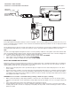
ROUTING WIRES:
The spark plug wires should be routed away from direct heat sources, such as exhaust manifolds and headers and any
sharp edges. The trigger wires should be routed separate from the other wires and spark plug wires. It is best if they are
routed along a ground plane such as the block or rewall which creates an electrical shield.
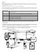
WARNING! The HyperSpark 2 EFI Ignition is a capacitive discharge ignition. High voltage is at the coil primary
terminals. Do not touch the coil or connect test equipment to the terminals.
-
+
AABB
C
C
AB
C
BAC
1
2
22 222
1
1
ADD’L OUTPUTS
(Refer to Sniper EFI
Instructions)
SNIPER TBI
ADD’L OUTPUTS
YELLOW -
COIL (-) NOT USED
HYPERSPARK
DISTRIBUTOR
PINK -
SWITCHED12V
PURPLE
MAG+
NOTE: CONNECT TO
IGNITION ADAPTER
(SUPPLIED WITH
DISTRIBUTOR)
TO 12V
KEYED
IGNITION
RED - SWITCHED12V
IGNITION 12V
WHITE - POINTS OUTPUT
PINK -
SW 12V
WHITE - POINTS OUTPUT
BLACK - BATTERY -
ORANGE -
COIL (+)
BROWN/
ORANGE -
COIL (-)
RED - BATTERY +
RED - BATTERY +
HYPERSPARK 2 WIRING DIAGRAM - SNIPER TBI
DIRECT TO
BATTERY
TERMINALS
TFI STYLE
CONNECTOR PLUG
& PLAY
*optional ring terminals
included
BATTERY
BLACK - BATTERY -