
User Guide

ASSEMBLY INSTRUCTIONS:
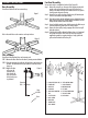
Base Assembly:
You will need the base and four extension legs.
Push in the small tab on each extension and snap into base
Pole Assembly:
You will need the completed base and extension pole.
STEP 1: Remove the base collar from the base by turning counter-clockwise.
STEP 2: Take the extension pole, with the solid end down, and insert it into
the base. The hollow end of the pole (with the screw hole) will be
facing up.
STEP 3: Replace the base
collar over the
extension pole,
slide it down the
pole, and secure it
to the base by turn-
ing clockwise.
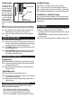
Fan Head Assembly:
You are now ready to assemble the fan head (See Figure #3)
Step 1: Position the rear grill over the motor shaft, making certain the 2
notches at the top and bottom of the rear grill fit over the 2
prongs on the motor housing. Please make sure the rear grill fits
securely against the motor housing.
Step 2: Secure the rear grill in its place using the rear grill mounting nut.
Turn this nut clockwise and tighten firmly.
Step 3: Slide the fan blade, with the hollowed interior of the blade facing
towards the rear grill firmly onto the motor shaft. Make sure the
shaft protrudes from the front of the blade.
Step 4: Secure fan blade onto the motor shaft by turning the blade cap in
a counter-clockwise direction until it is firmly in place.
Step 5: Prepare the front grill by simply snapping the circular front grill
logo plate in place.
Step 6: Center the front grill by aligning the Holmes logo so it is horizontal
and parallel to the floor. Then secure the front and rear grills
completely together by snapping into place. Lastly, tighten the
grill screw at the bottom of the rear grill.
A. LOGO PLATE (SNAP ON)
B. FRONT GRILL
C. BLADE CAP
D. FAN BLADE
E. REAR GRILL MOUNTING
NUT
F. PLASTIC BAND
G. GRILL SCREW
H. REAR GRILL
I. MOTOR SHAFT
J. GRILL MOUNT
K. SPEED CONTROL KNOB
L. OSCILLATION BAR
M. MOTOR HOUSING
N. TILT JOINT
O. TILT ADJUSTMENT KNOB
P. FAN POST SCREW
Q. BASE COLLAR
A
N
B
C
D
E
O
F
G
H
I
M
J
K
L
(fig 4)
P
Q
Base
Collar
Extension
Pole
Base
Figure 1
Figure 2
Figure 3