PROGRAMMABLE INDICATORS CONTROLLERS AND PROCESS 60 SERIES User Guide Version 3.
60 SERIES User Guide Version 3.
GSE 60 Series User Guide Copyright © 2000 GSE Scale Systems. All rights reserved. Published by: GSE Scale Systems 42860 Nine Mile Road Novi, MI 48375 USA Information in this User Guide is subject to change without notice due to correction or enhancement. The information described in this manual is solely the property of GSE.
CONTENTS 1 CHAPTER 1: INTRODUCTION................................................................ 1 COMMON WEIGHING APPLICATIONS ................................................................. 1 FEATURES ......................................................................................................... 2 CONTROLLER DESCRIPTIONS ............................................................................ 2 DISPLAY ......................................................................................
0 SERIES INDICATORS PERFORMING ACCUMULATIONS...................................................................... 35 INITIALIZING ACCUMULATION TOTALS .......................................................... 35 6 CHAPTER 6: ADDITIONAL OPERATING MODES............................37 PIECE WEIGHT DATABASE MODE – APW LOOKUP ....................................... 37 Store APW – Store a specific APW to the database – Must Perform a sample before using. .........................................................
CHAPTER 1:INTRODUCTION SETUP MODE ERROR MESSAGES..................................................................... 58 HARDWARE PROBLEM ERROR MESSAGES ...................................................... 59 CALIBRATION ERROR MESSAGES.................................................................... 60 GENERAL ERROR MESSAGES .......................................................................... 61 MISCELLANEOUS MESSAGES ..........................................................................
1CHAPTER 1: INTRODUCTION GSE 60 Series programmable indicators come standard with a number of features that make them the most versatile and powerful systems in their price class. Accurate and durable, 60 Series controllers will provide you with years of quality weighing service even in the most demanding industrial environments. This User Guide contains basic operating information.
60 SERIES INDICATORS FEATURES GSE 60 Series controllers share the following standard features: • Sealed elastomer keypad for protection against harsh environments • Capability to power as many as 14 350-ohm load cells for demanding applications (12 350-ohm load cells on 460 and 465) • AC/DC power operation • Front panel calibration and linearization execution • Full scale response time from 0.06 to 8 seconds • Selectable weighing units: pounds, kilograms, ounces, grams, etc.
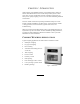
CHAPTER 1:INTRODUCTION DISPLAY Display types differ according to model. The table below describes the display(s) offered for each controller. Table 1: 60 Series Displays Model 460, 465, 560 660 661 562, 662 663 665 Display 6 digit, Vacuum Florescent display (VFD) 0.
60 SERIES INDICATORS Figure 2: 6 Digit Vacuum Fluorescent Display (VFD) Figure 3: 4x20 Vacuum Fluorescent Display (VFD) Figure 4: 240x64 Backlit LCD Display Figure 5: 240x128 Backlit LCD Display Figure 6: 6 Digit VFD and 4x20 VFD 4
CHAPTER 1:INTRODUCTION KEYPAD A sealed elastomer keypad comes standard on all 60 Series controllers. A TTL alpha keypad is also available as an option on the model 663 controller. For more information on the alpha keypad option, please refer to the 60 Series Technical Reference Guide. Detailed descriptions of each key and its associated function follow below.
60 SERIES INDICATORS Figure 9: 660 Series Keypad ZERO Press [ZERO] to zero the current quantity/weight reading. When the meter is at Center Zero center-of-zero indication will appear on the upper line of the dot matrix display. If a Custom Unit’s name is greater than 2 characters, the Center Zero indication is not displayed. If in the quantity mode, pressing [ZERO] will set the current mode to a gross zero quantity. If in the Weigh Mode, pressing [ZERO] sets the current mode to Gross Weight.
CHAPTER 1:INTRODUCTION [F2] The [F2] key is used as a function key (such as accessing a menu or starting a process). 560 and 660 Series only. Not available on Model 460 or Model 465. [F3e] The [F3e] key is used as a left arrow key for scrolling or as a function key (such as accessing a menu or starting a process). Not available on Model 460 or Model 465. [F4d] The [F4d] key is used as a down arrow key for scrolling or as a function key(such as accessing a menu or starting a process) .
60 SERIES INDICATORS Figure 10: 460 Keypad Table 2: 460 Key Functions KEYPRESS [ZERO / CLEAR] [PRINT] [UNITS] [TARE / ENTER] [SELECT] GROSS/NET QTY OTHER MODES Zero Scale Zero Quantity Print custom transmit Toggle though enabled units Tares Scale Print custom transmit ZERO * CLEAR † Character Entry ▲ N/A Space ► Tares Scale ENTER Selects Parameters Selects Parameters SELECT Multiple Key Combinations [ZERO] + [PRINT] [ZERO] + [TARE] [ZERO] + [UNITS] [PRINT] + [UNITS] [PRINT] + [SELECT] [TA
CHAPTER 1:INTRODUCTION OPTIONS Numerous hardware options that maximize the capabilities and functions of the standard 60 Series controllers are available. These options can be installed by your GSE distributor when you order your controller or added later. All options must be installed by your GSE distributor or a qualified technician. Please do not return the controller to GSE for installation of options. Consult your GSE products distributor for installation instructions.
60 SERIES INDICATORS DeviceNet Module Provides a communication path between multiple end-points (Devices). The GSE indicator will act as a slave on the network device layer. Dura-Shield A clear weatherable film lexan that adheres over the keypad and display. Recommended when high-pressure washdown, petroleum distillates or harsh cleaning agents are present. (Not available for the 663). Ethernet Module Communicate via internet or intranet connection.
CHAPTER 1:INTRODUCTION SPECIFICATIONS Performance • Full Scale Selectable • Resolution 100,000 displayed (+/-500,000 internal) • Display Update Selectable 0.05-20 seconds • A/D Conversion 60 Hz • Non-Linearity 0.005% of full scale (input dependent) • Zero Track 0.05-20.0 displayed divisions • Zero Range Selectable from 0.01-100% of full scale • Calibration Selectable, 5 multi-point calibration for linearization • Division Size .
60 SERIES INDICATORS • Selectable data formatting Display • Vacuum fluorescent, 0.75 in. high digits • 240x64 LCD display, 5 in. x 1.34 in. usable area • 240 x 128 LCD display, 4.72 in. x 2.52 in. usable area • Four-line by 20-character alphanumeric display, 0.20 in.
CHAPTER 1:INTRODUCTION 13
2CHAPTER 2: INSTALLATION This chapter outlines the basic installation of the 60 Series instruments. Please take the time to review these important guidelines. IMPORTANT! The 60 Series indicators do not include an on/off switch, and therefore must be installed near a power outlet socket that is easily accessible and in keeping with UL/CSA safety standards.
60 SERIES INDICATORS polycarbonate material, which may scratch due to aggressive cleaning. Care must be taken to avoid such damage. Connections from the load cell to the single channel input require gaining access to J1 inside the sealed enclosure. In addition, peripherals and options can be interfaced to 60 Series instruments by means of connections within the enclosure. However, physically accessing the unit may void the warranty.
CHAPTER 2:INSTALLATION MODEL 460 OUTLINE DRAWINGS Figure 11: 460 Standard Enclosure Figure 12: 460 Panel Mount Enclosure 17
60 SERIES INDICATORS MODEL 465, 560, 562, 660, 661, 662 OUTLINE DRAWINGS Figure 13: Standard Enclosure (excluding 460, 663, 665) Figure 14: Panel Mount Enclosure (excluding 460, 663, 665) 18
CHAPTER 2:INSTALLATION MODEL 663 OUTLINE DRAWINGS Figure 15: Model 663 Standard Enclosure Figure 16: Model 663 Big Box Enclosure 19
60 SERIES INDICATORS MODEL 665 OUTLINE DRAWINGS Figure 17: Model 665 Standard Enclosure Figure 18: Model 665 Panel Mount Enclosure 20
CHAPTER 2:INSTALLATION PANEL MOUNT CUTOUTS Figure 19: Model 460 Panel Mount Cutout Figure 20: Model 465, 560, 562, 660, 661, 662 Panel Mount Cutout 21
60 SERIES INDICATORS Figure 21: Model 665 22
3CHAPTER 3: CALIBRATION The 60 Series indicators can be calibrated several ways. The following method is a quick calibration procedure and assumes that the necessary parameters are selected before the actual calibration is performed (i.e. full scale value, graduation size, etc.). Your local GSE distributor will normally set up these parameters. QUICK CALIBRATION A certified weight is required to perform a calibration. Serious inaccuracies could result from using non-certified standards for calibration.
60 SERIES INDICATORS The calibration selections are as follows, starting with New Zero?: • New Zero? • Last Zero? • Temp Zero? • Only Zero? • Cal Reset • Known Load Cell • NEW ZERO? New Zero? is the selection for establishing the first or a new calibration. If New Zero? is selected, the controller displays the dead load (which might not be in precise units) that is present on the scale. The controller assumes a “NO LOAD” condition. Remove the load, and press [ENTER].
CHAPTER 3:CALIBRATION • If the calibration is not accurate, press [CLR]. The controller will return to the New Zero? prompt. Repeat the above steps to calibrate. If the calibration weight was less than 5% of capacity, or if there was a large change in the calibration, the controller prompts ReCal Req’d. Press [ENTER] and repeat the calibration, or press [CLR] to obtain the CAL OK? prompt as described above and override the re-calibration requirement.
60 SERIES INDICATORS TEMP ZERO? Temp Zero? is used to recalibrate without establishing a new zero. In some applications you might want to perform a calibration without removing the currently applied load. This is particularly useful in tank weighing applications where it is both time-consuming and costly to drain the tank being weighed. During the calibration procedure, at the Temp Zero? prompt you press [ENTER].
CHAPTER 3:CALIBRATION 1. Remove all weight from the scale. 2. Access the Calibration Mode (see page 23). 3. Press [SELECT] to toggle to the Only Zero? routine. 4. At the Only Zero? prompt, press [ENTER]. The displayed value zeroes out. Adj Zero! is displayed briefly, followed by CAL OK?. 5. Press [ENTER] to accept the newly established zero, or [CLR] to repeat the calibration. 9. At the Enter = Save prompt, press [ENTER] 10.
60 SERIES INDICATORS Once the Cal Reset is performed, the controller returns to the New Zero? prompt. Press [SELECT] to toggle to the desired calibration routine. Following a Cal Reset, a re-calibration should be performed before exiting the calibration or Setup Modes. The reset will not be saved unless a recalibration is performed and changes are saved. KNOWN LOAD CELL? Known Load Cell is used to calibrate without test weights. The exact full scale mV/V rating must be known for each load cell.
CHAPTER 3:CALIBRATION 9. Key in the full scale capacity for the load cell(s) and press [ENTER]. For the Model 460, use the [PRINT] and [UNITS] keys to enter numeric values. Refer to Table 2: 460 Key Functions on page 8. - or Press [ENTER] to accept the displayed value. 10. The display briefly shows Updtg Gains as it updates the gain values, then prompts CurWt Zero?. 11. Press [ENTER] to establish the current input signal as the zero reference. - or Press [SELECT] to display Zero=0mVv?.
60 SERIES INDICATORS check the accuracy of the calibration by weight without leaving the Calibration Mode. If the calibration was accurate, press [ENTER]. The indicator will prompt you to save the new calibration plus any other changes you made. Press [ENTER] to save, then [ENTER] again to exit. If the calibration is not accurate, press [CLR]. The indicator will return to the New Zero? prompt.
4CHAPTER 4: COUNTING MODE The front panel keys on the 60 Series take on different functions depending on the selected mode. This chapter will define the front panel key operation for the Counting Mode. COUNTING MODE (KEY OPERATION) To activate the counting operation, the indicator must be in the Quantity mode. To access the Quantity mode on a Model 460, the quantity mode must be in the selectable modes of instrument operation.
60 SERIES INDICATORS NEGATIVE SAMPLING TO DETERMINE A PIECE WEIGHT In order to perform a negative sample routine, access the Quantity mode, place a full or partially full container of parts on the scale, and press [ENTER]. The indicator will then perform an auto-tare resulting in a zero net weight. The display will then prompt you to Add xx where the "xx" is the sample size. In this case, the prompt Add xx actually means take parts from the container.
CHAPTER 4:COUNTING MODE 3. Press [ENTER]. The indicator tares to a zero net weight. The display shows the current net weight and the prompt: Add 10. 4. Place the specified number of parts on the scale. 5. Press [ENTER]. The indicator then calculates the piece weight of the sample parts and momentarily displays the maximum number of parts which may be added for a piece weight enhancement to occur. The minimum achieved accuracy is then displayed. 6.
60 SERIES INDICATORS COUNTING MODE LISTING The [SELECT] key will advance to the next mode. Alternatively, keying a mode number then pressing [SELECT] will change the current mode to be the mode whose number was keyed in. The following six modes are counting related. Any one of these parameter numbers listed may be printed out on a ticket.
5CHAPTER 5: ACCUMULATION MODE 60 Series controllers offer three main memory registers into which weighing data may be accumulated. The three registers are the Gross Total, Net Total and the Quantity Total. PERFORMING ACCUMULATIONS First, enter the desired “Accumulation Mode” either by pressing the [SELECT] key until one of the Accumulation Modes appears on the display or key in one of the accumulation parameters directly. Refer to Table 4: Accumulation Mode Numbers on page 36.
60 SERIES INDICATORS The [ZERO] + [ENTER] keys on the Model 460 or the [CLR] key on all other 60 Series may be used to reset both the net and Gross Totals to zero. The prompt CLEAR ACS? will appear briefly followed by ENTER =CLR!. Press [ENTER] to complete the clearing or press any other key to abort the clear operation.
6CHAPTER 6: ADDITIONAL OPERATING MODES We have taken popular application files and incorporated them into the firmware in an easy to use menu format. Use the arrow keys to scroll through the choices or the [SELECT] key on the Model 460 and press [ENTER] to setup the chosen application file. An explanation of each application file can be found at the bottom of the display on the LCD models only. With 5 different display choices available on the 60 series instruments, menu selections may vary in appearance.
60 SERIES INDICATORS Note: If the ID# does not exist you will be prompted to add default number of pieces to store a new APW. [CLR] will abort the process. PRINT APW’S – PRINTS ALL STORED RECORDS IN ROW/COLUMN FORMAT. 1. 2. 3. 4. Press [TARGET] or [F2]. Prompt = “Delete ID# XXX?”. Press [CLR/NO] to advance to print mode. Press [ENTER] to print stored APW’s in row/column format. Indicator returns to the gross mode. CLEAR ONE APW – CLEARS CURRENT RECORD FROM THE DATABASE. 1. 2. Press [TARGET] or [F2].
CHAPTER 6:ADDITIONAL OPERATING MODES TRUCK IN/OUT (MODELS 465,560,562 AND 660 SERIES) Used for vehicle weighing where product is being loaded or unloaded. TRUCK IN Weigh the vehicle in. 1. 2. 3. 4. With the truck on the scale. Press [F1]. Prompt = “Key In ID#”. Press [ENTER] for Automatic ID# or key-in the ID number and press [ENTER]. The indicator flashes Weigh In and returns to the gross mode. If a printer is connected, a ticket will automatically be printed.
60 SERIES INDICATORS 1. 2. 3. 4. 5. 6. Press [TARGET] or [F2]. Prompt = “Print ID’s?”. Press [CLR/NO]. Prompt = “Clear One?”. Press [ENTER]. Prompt = “ID to Delet”. Key in the ID number to be deleted and press [ENTER]. If the ID number is not stored in the database, “Not Found” will be displayed briefly. The indicator returns to the weigh mode. Otherwise, if the ID number was found “Done” will be displayed briefly and the indicator will return to the weigh mode.
CHAPTER 6:ADDITIONAL OPERATING MODES CHECK WEIGH ABSOLUTE AND PERCENTAGE OPERATION The standard check-weigh operation is designed to check the weight of an item against a given standard or target weight. In the check weigh absolute mode, values are entered as target limits. In the check weigh percent mode, the values are entered based on percentage. SET THE HI AND LO WEIGHTS (460) 1. 2. 3. 4. 5. 6. Press [SELECT] until prompt = “mName SETUP”. Press [TARE] prompt =”10.
60 SERIES INDICATORS Note: if the weight is greater than the high limit then the prompt OVER” is displayed. If the weight is less than the low limit the prompt “UNDER” is displayed. If the weight is between the high and low limits then prompt “GOOD” is displayed. BATCHING OPERATION (465,560 AND 562) FILL SETTING SETPOINTS, PREACT, AND DRIBBLES 1. 2. 3. 4. 5. 6. 7. 8. Press [TARGET] or [F2] prompt = “current setpoint value + SP 1”. Key in Setpoint value.
7CHAPTER 7: TIME AND DATE (CLOCK FEATURE) The 560 and 660 Series indicators include a battery backed time/date feature. The 460/465 have an optional battery backed time/date module. Without this option on the 460 Series, the time/date will be reset when power is lost. This means that when the feature is used, the time and date does not need to be entered every time the instrument is powered up. The time/date feature permits printouts with time and day of the week and the date in many possible formats.
60 SERIES INDICATORS displayed. Press [ENTER] if the date is correct and move to the Time setting mode. The new time is entered by keying in "HH.MM.SS" in a 24-hour format. Hours and minutes entries must be separated by a decimal point. Seconds entry is optional, and if omitted, they are set to zero. To specify seconds, it also must be separated from minutes by a decimal point. Leading zeroes need not be entered. For example, if you enter "8.9.
8CHAPTER 8: LEGAL-FOR-TRADE The 60 Series parameter setup does not ensure compliance with legal-fortrade installations as mandated by local weights and measures authorities. This chapter explains how to configure the 60 Series controllers to comply with various regulations and describes other features that will make your controller suitable for installations worldwide. Legal-for-trade requirements vary by location. Ensure that your controller is installed in accordance with all local regulations.
60 SERIES INDICATORS NTEP The National Type Evaluation Program (NTEP) is a widely accepted weights and measures standard in the United States. Most states abide by some or all of the requirements set forth by NTEP. A complete list of these regulations is available in the “Handbook 44” publication distributed by the National Institute of Standards and Technology (NIST). For more information on this and other NIST publications, visit their web site at http://www.nist.gov.
CHAPTER 8:LEGAL-FOR-TRADE NTEP CUSTOM SETUP The “Custom Setup” parameter, P60205 of the information parameters, displays a list of parameters, which, if configured improperly, could facilitate fraud in a legal-for-trade installation. A weights and measures inspector might check this parameter and inquire about the configuration of any parameters that appear in this list.
60 SERIES INDICATORS P205 will appear in the “Custom Setup” list for each receive port enabled. For example, if the receive mode is enabled for all four ports, the list will display P205—, P205˜, P205™, and P205š. P240 – Minimum Transmit Width A weight value that cannot be displayed due to the 6-digit limitation of the standard VF display may not be printed. To ensure this is not possible, P240 must be set to a width of not greater than 7 (6 digits and a decimal point). NTEP must also be enabled at P440.
CHAPTER 8:LEGAL-FOR-TRADE SEALING AND AUDIT TRAILS Most legal-for-trade installations will require the indicator to be sealed. A sealed indicator cannot be accessed for setup or calibration changes without breaking a physical seal or incrementing an event counter, thus providing evidence that the unit has been tampered with.
60 SERIES INDICATORS 60 Series Standard Enclosure NTEP Seal 50
CHAPTER 8:LEGAL-FOR-TRADE Panel Mount NTEP Seal 51
SERIES INDICATORS 663 NTEP Seal 52
CHAPTER 8:LEGAL-FOR-TRADE 665 NTEP Seal 53
60 SERIES INDICATORS AUDIT TRAIL PARAMETERS Three separate incrementing, non-resettable audit trail parameters are used by the M660 to indicate changes to various parameters: • P60201 – OIML • P60203 – Calibration • P60204 – Setup An audit trail counter will increment only once upon exiting the Setup Mode and saving changes regardless of how many settings were changed. Each audit trail counter will increment to 99999 before beginning again at 00001.
CHAPTER 8:LEGAL-FOR-TRADE • P410, P412 OIML Enable, Preset Enable • P420 Standard VF Display Mode • P600 Æ P646 Rename Parameters • P800 Æ P820 Key Functions • P989 Æ P4999 Custom Transmit • P61101 Æ P61140 Calibration & Linearization • P65001, P65002 Default All, Default –Cal Calibration Audit Trail Any changes to the existing calibration will increment the Calibration audit trail at P60203. This includes any changes to P60101 Æ P61140 of the information parameters.
9CHAPTER 9: TROUBLESHOOTING This chapter of the User Guide provides information on error messages and trouble-shooting 60 Series controllers. Some information in this chapter refers to parameters that are not discussed in this guide. They are provided as a quick reference to problems and solutions. Please refer to the technical reference manual or consult your GSE distributor for additional information. All 60 Series error messages are listed below in numerical order.
60 SERIES INDICATORS 06 Tare>F.S.! Tare entry was greater than full scale. Most likely the entered tare value was incorrect. 07 Tare < 0 ! Negative tare attempted, but not allowed per P162. For auto-tares, the GROSS Weight must be greater than zero unless P162 is changed to allow negative tares. 08 CheckConn. Displayed if the signal into the A/D is +/- 2 times the Full Scale signal.
CHAPTER 9:TROUBLESHOOTING HARDWARE PROBLEM ERROR MESSAGES 17 A/D BAD! The processor has detected a problem with the A/D chip. Contact your GSE distributor. 18 BufSzMax! The accumulative total buffer size for both the TX and RX buffers of all four COMM ports is 4096 bytes. Displayed If entries to the “buffer size” parameters (P207-P208) exceed this total. 19 x06\x44\x61ta&Stop Certain combinations of protocol are not available. The protocol combination selections are in P201, P202 and P203.
60 SERIES INDICATORS 28 NoRAMAVAIL The current setup requires more RAM than is currently installed. Either contact your dealer or the manufacturer. 29 PIN error This message will appear on power-up or setup if the E2 is corrupted in the PIN section. Check E2 for problems. The access code is defaulted to the manufacturer (GSE) access code. Also check Error 11. CALIBRATION ERROR MESSAGES 30 F.S.
CHAPTER 9:TROUBLESHOOTING 34 RES> 25K! The current combination of capacity P110 and increment P111 result in a resolution greater than 25,000 graduations. This is simply a warning in case this was not intended. 35 RES>100K! The current combination of capacity P110 and increment P111 result in a resolution greater than 100,000 graduations. This is not allowed and as soon as any key is pressed the instrument will jump back into the Setup Mode to parameter P110 to verify the settings.
60 SERIES INDICATORS MISCELLANEOUS MESSAGES EntryError This error message is the most commonly used. The primary causes are entering a value preceding a key (such as [ZERO]) which is not allowed, entering alpha data for a numeric selection, or entering a fractional value for an entry which only accepts whole numbers. Occurs in Setup Mode or an operational mode. WhichTx#? The instrument is setup with more than one custom transmit with parameter P991 set for Prmpt (Prompt) and the [PRINT] key is pressed.
CHAPTER 9:TROUBLESHOOTING tx on hold or the factory. To prevent the problem, try reducing the baud rate (P200). This will occur if a data transmission is held up for two seconds of more due to a de-asserted handshake. Refer to the description of parameter P206 in the technical reference manual for more information. tx abort This occurs if the [CLR] key is pressed when the tx on hold error message is shown or if P206 is set for abort and the transmit buffer becomes full.
Your GSE Distributor is: PART NUMBER: 39-10-37149